xi
About this Manual:
This manual describes ladder diagram programming and memory allocation in the SYSMAC CV-series Program-
mable Controllers (PCs) (CV500, CV1000, CV2000, and CVM1). This manual is designed to be used together with
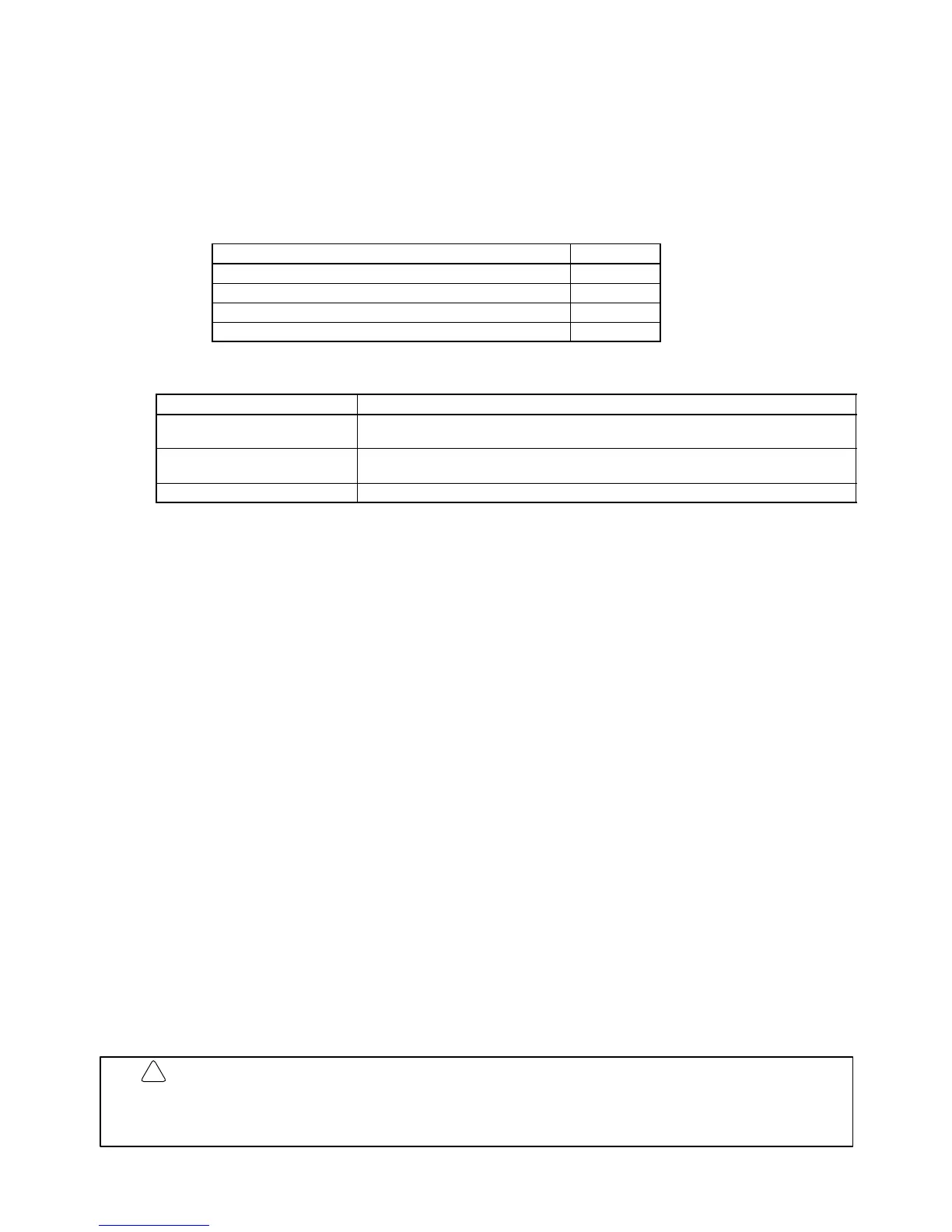
two other CV-series PC operation manuals and an installation guide. The entire set of CV-series PC manuals is listed
below. Only the basic portions of the catalog numbers are given; be sure you have the most recent version for your
area.
Manual Cat. No.
CV-series PC Installation Guide W195
CV-series PC Operation Manual: SFC W194
CV-series PC Operation Manual: Ladder Diagrams W202
CV-series PC Operation Manual: Host Interface W205
Programming and operating CV-series PCs are performed with the CV Support Software (CVSS), the SYSMAC Sup-
port Software (SSS), and the CV-series Programming Console for which the following manuals are available.
Product Manuals
CVSS The CV Series Getting Started Guidebook (W203) and the CV Support Software Opera-
tion Manuals: Basics (W196), Offline (W201), and Online (W200).
SSS SYSMAC Support Software Operation Manuals: Basics (W247), C-series PC Opera-
tions (W248), and CVM1 Operations (W249)
CV-series Programming Console CVM1-PRS21-E Programming Console Operation Manual (W222)
Note The CVSS does not support new instructions added for version-2 CVM1 PCs. The SSS does not support SFC
programming (CV500, CV1000, or CV2000).
Please read this manual completely together with the other CV-series manuals and be sure you understand the infor-
mation provide before attempting to install, program, or operate a CV-series PC. The basic content of each section of
this manual is outlined below.
Section 1
gives a brief overview of the history of Programmable Controllers and explains terms commonly used in
ladder-diagram programming. It also provides an overview of the process of programming and operating a PC. A list
of the manuals available to use with this manual is also provided.
Section 2
provides information on hardware aspects of the CV-series PCs relevant to programming and software
operation. This information is covered in more detail in the
CV-series PC Installation Guide
.
Section 3
describes the way in which PC memory is broken into various areas for different purposes. The contents of
each area and addressing conventions are also described.
Section 4
explains the basic steps and concepts involved in writing a basic ladder diagram program. The entire set
of instructions used in programming is described in
Section 5 Instruction Set
.
Section 5
explains each instruction in the CV-series PC instruction sets and provides the ladder diagram symbols,
data areas, and flags used with each. The instructions provided by the CV-series PCs are described in following sub-
sections by instruction group.
Section 6
explains the execution cycle of the PC and shows how to calculate the cycle time and I/O response times.
I/O response times in Link Systems are described in the individual System Manuals. These manuals are listed at the
end of
Section 1 Introduction
.
Section 7
provides tables that list the parameters in the PC Setup, provide examples of normal application, and
provides the default values. The use of each parameter in the PC Setup is described where relevant in this manual
and in other CV-series manuals.
Section 8
provides information on hardware and software errors that may occur during PC operation. Although de-
scribed mainly in
Section 3 Memory Areas
, flags and other error information provided in the Auxiliary Area are listed in
8-5 Error Flags
.
Various appendices are also provided for convenience (see table of contents for a list).
WARNING Failure to read and understand the information provided in this manual may result in
personal injury or death, damage to the product, or product failure. Please read each
section in its entirety and be sure you understand the information provided in the section
and related sections before attempting any of the procedures or operations given.
!