4-14
Chapter 4 I/O SETTINGS
ZW
User’s Manual
Chapter 4
Settings for I/O
■ Setting focus
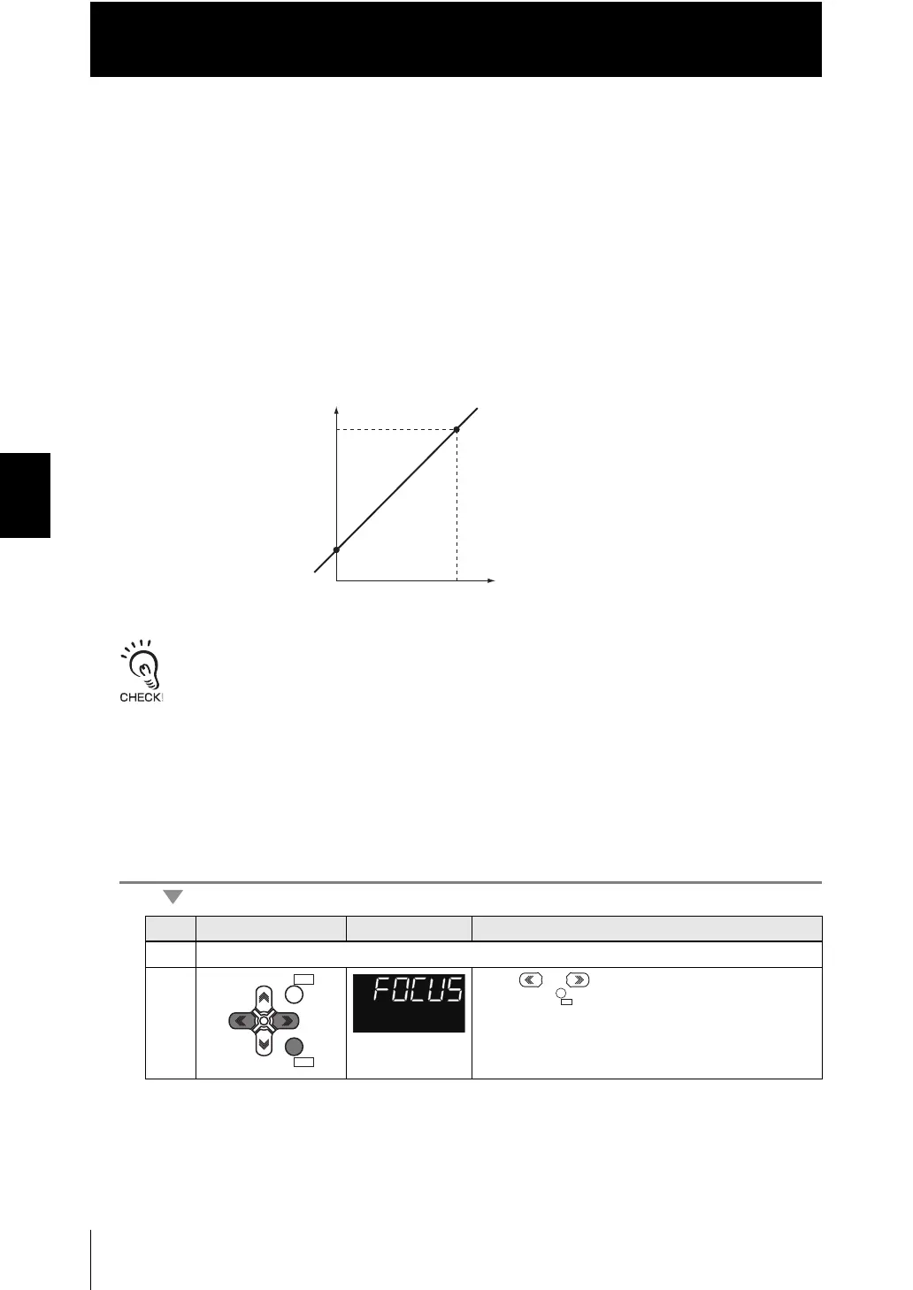
For the analog output, because the measured value is converted to a current of 4 to 20
mA or a voltage of -10 to +10, and is then output, you can freely set the relationship
between the displayed measured value and output value.
Match the settings to suit the connected external device.
Enter the output values for any two current values or voltage values to set the output
range.
Example: When setting 4 mA output (Point 1) for measured value of 0 mm and 20 mA
output for measured value of 6 mm (Point 2) (current output)
Separate the two specified points by at least 1% of the rated measuring range of the connected Sensor
Head or 40 m.
For example, for a ZW-S40, the two measured points must be separated by at least 12 mm x 0.01 = 0.12
mm as the measuring range is 12 mm (6 mm).
As an example, here is an explanation of the procedure for setting 4 mA output (Point
1) for measured value of 0 mm and 20 mA output for measured value of 6 mm (Point
2).
Operating procedure
Steps
Key operation Display Description
1 - 3 For moving to ANALOG, see steps 1 to 3 in p.4-12
4 Press or keys to select either of "FOCUS"
and press key.
6
4
0
20
0
Measured value
(mm)
Output current
(mA)
Point 1
Point 2
ZERORST/ZERORST/
ESCESC
ZERO/ZERO/
SETSET
 Loading...


