4-16
Chapter 4 I/O SETTINGS
ZW
User’s Manual
Chapter 4
Settings for I/O
■ Correcting analog output values
Discrepancies may occur between the current value/voltage value output as analog set
on the Controller and the current value/voltage value actually measured due to the
conditions for the connected external device or other factors.
The analog output correction function can be used to correct this discrepancy.
The output values are corrected by entering the correction value for the current or
voltage values for any two points. (Setting range: -999 to +999, default value: 0)
Set the output type and select either current or voltage output beforehand. Also, connect the analog
output signal line to an external ammeter or voltmeter.
As example, here is an explanation of the procedure for correcting 4 mA output (Point
1) and 20 mA output (Point 2).
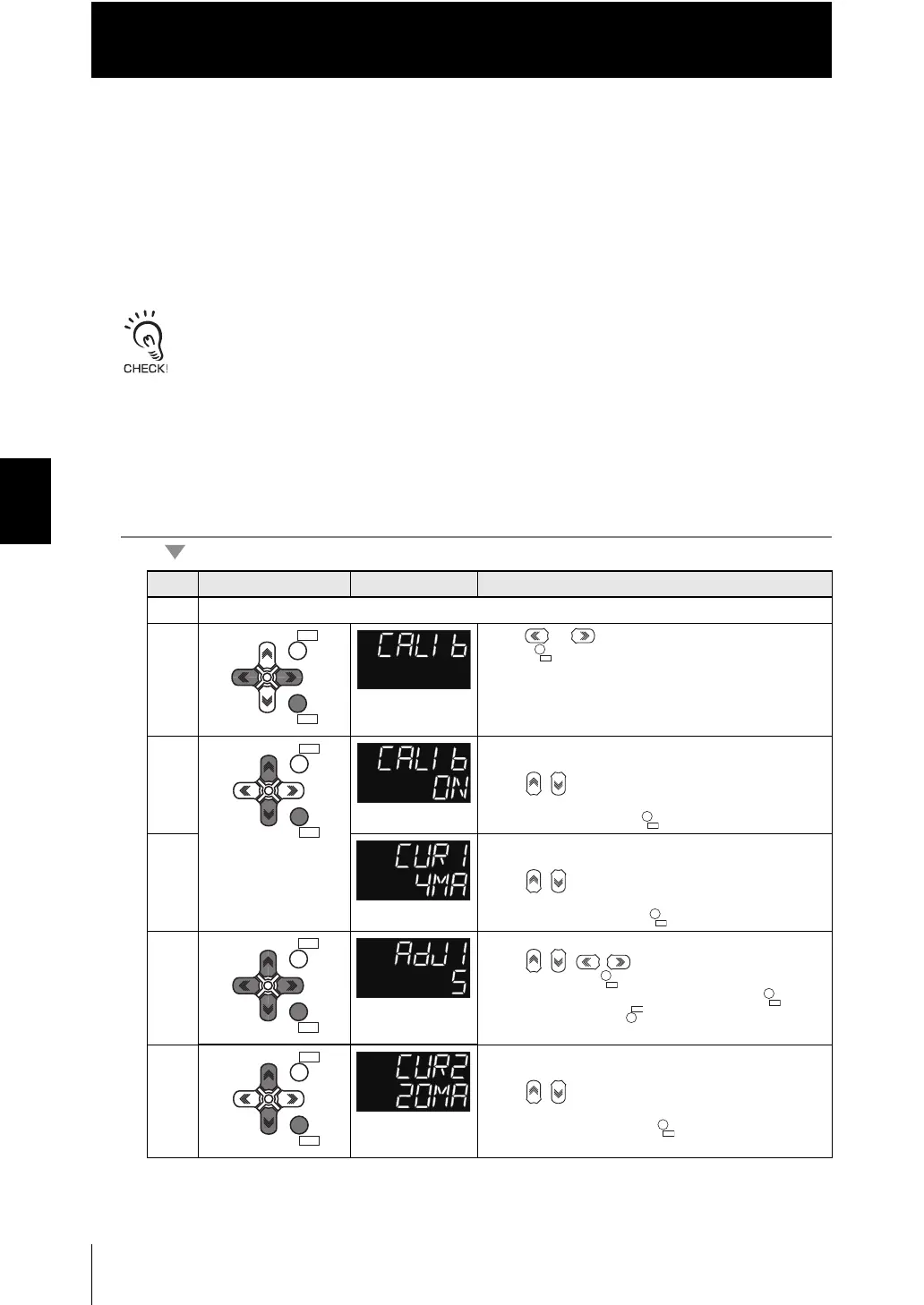
Operating procedure
Steps
Key operation Display Description
1 - 3 For moving to ANALOG, see steps 1 to 3 in p.4-12
4 Press or keys to select either of "CALIB" and
press key.
5 The current setting value is displayed on the sub-
display.
Press / keys to enter the editing mode, and the
sub-display blinks.
Select "ON" and press key.
6 The current set value for Point 1 is displayed on the
sub-display.
Press / keys to enter the editing mode, and the
sub-display blinks.
Select "4mA" and press key.
7 Correct the Point 1 output.
Press / / / keys to input the correction
value and press key.
Next, check the ammeter value and press key.
To re-adjust, press key.
8 The current set value for Point 2 is displayed on the
sub-display.
Press / keys to enter the editing mode, and the
sub-display blinks.
Select "20mA" and press key.
ZERORST/
ESC
ZERO/
SET
ZERORST/
ESC
ZERO/
SET
ZERORST/
ESC
ZERO/
SET
ZERO/
SET
ZERORST/
ESC
ZERO/
SET
 Loading...


