4-40
Chapter 4 I/O SETTINGS
ZW
User’s Manual
Chapter 4
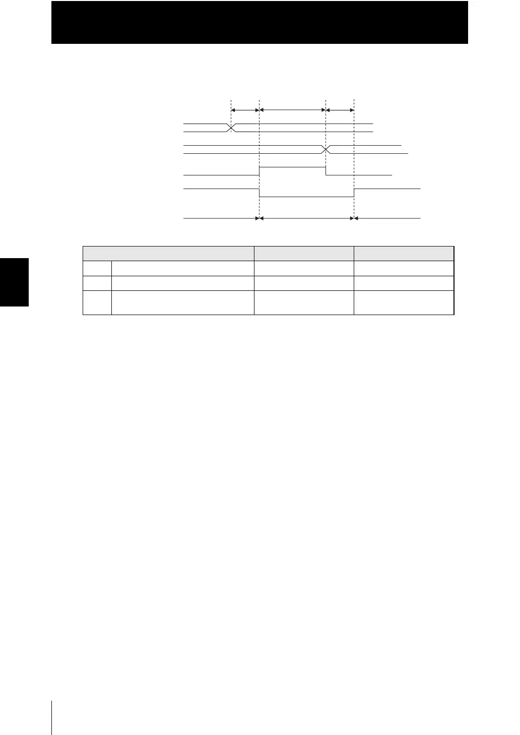
Timing Charts
■ Bank switching
●
Explanation of operations
(1) The BANK_SEL signal is switched to the bank number switched to.
(2) After the input response time, the measurement stops and the BUSY signal is
turned ON, then the bank switching operation is started.
(3) After the bank switching ends, the BUSY signal is turned OFF and the
BANK_OUT signal is switched.
(4) After the bank switching ends, the BUSY signal is turned OFF and the
BANK_OUT signal is switched.
Item Minimum Maximum
T7 Response time of input - 200 ms
T8 Bank switching time - 100 ms
T9 Measurement start response time 3T0 Depends on the set
conditions
(1) (2)
T7
BANK_SEL input
(BANK_SEL1/2/3)
T8
(3) (4)
T9
㪦㪥
㪦㪝㪝
㪦㪥
㪦㪝㪝
Measurement
BUSY output
ENABLE output
BANK_OUT output
(BANK_OUT1/2/3)
Clamp
Measurement
Measurement
 Loading...


