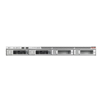
Note:
The heatsink is keyed to go on only one way. The captive screws that attach to
the pin 1 end of the socket stiffener frame are closer together than the captive
screws that attach at the opposite end of the stiffener frame.
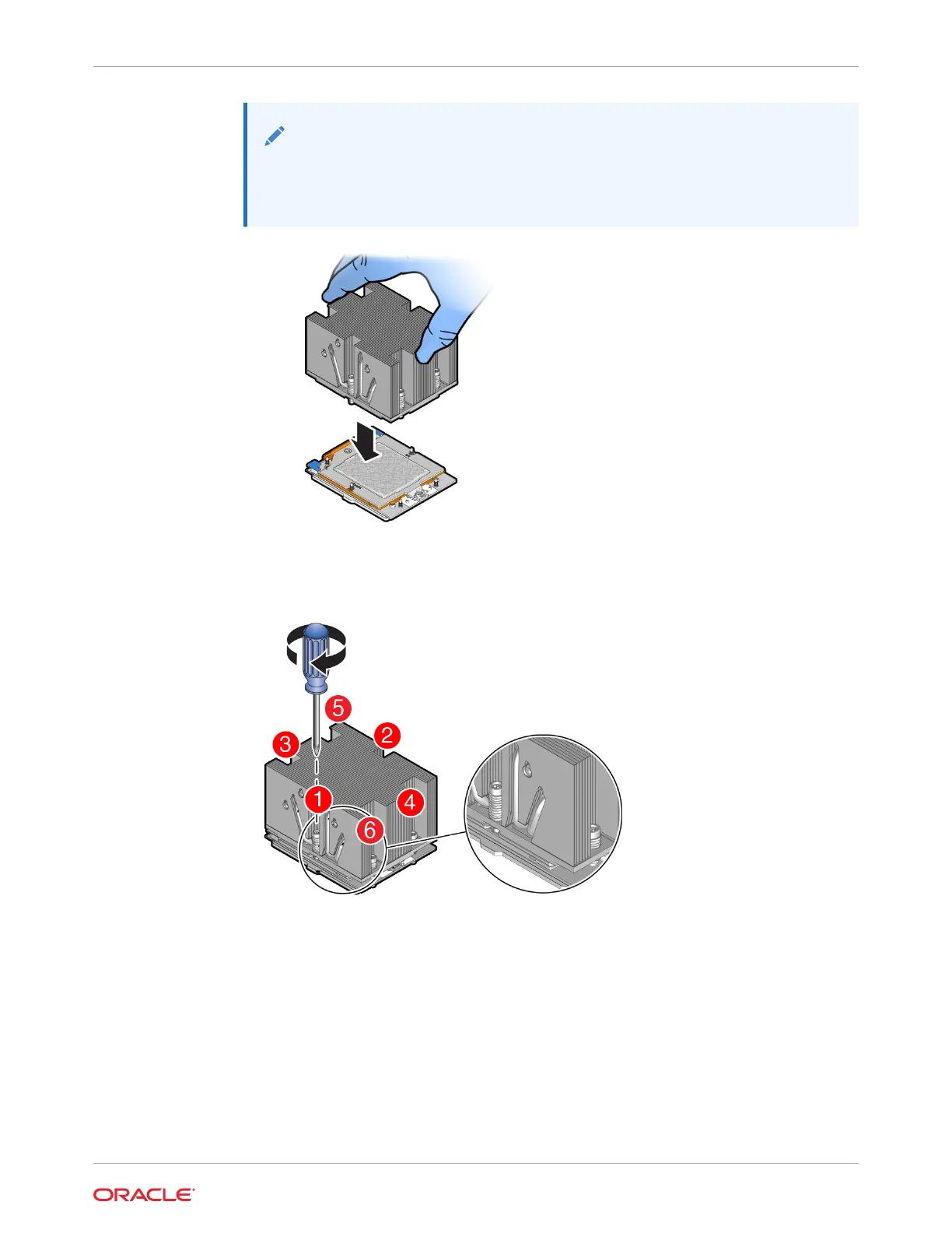
9. Tighten captive screws 1, 2, 3, 4, 5 and 6 in the order shown.
Using a 12 in-lbf (1.35 Nm/13.5 kg-cm) torque driver with a Torx T20 bit, tighten the
heatsink module to the socket, as shown in the following illustration.
a. Engage captive screws 1, 2, 3, 4, 5 and 6 in the order shown in the illustration.
b. Tighten captive screws 1, 2, 3, 4, 5 and 6 in the order shown in the illustration from
12 in-lbf (13.5 kg-cm) to 13.02 in-lbf (15.0 kg-cm).
Chapter 13
Install a Processor
13-17