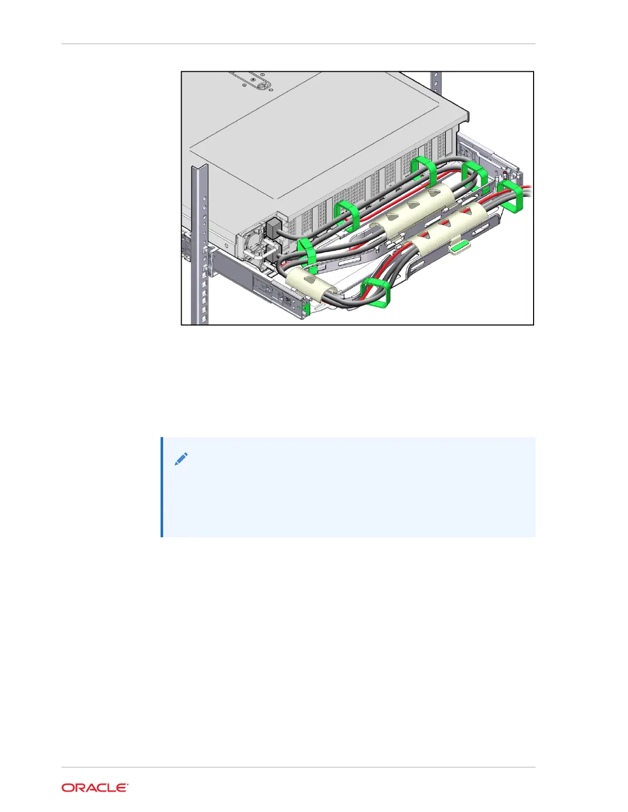
13. Ensure that the secured cables do not extend above the top or below the bottom
of the server to which they are attached.
Otherwise, the cables might snag on other equipment installed in the rack when
the server is extended from the rack or returned to the rack.
14. If necessary, bundle the cables with additional Velcro straps to ensure that they
stay clear of other equipment.
Note:
If you need to install additional Velcro straps, wrap the straps around the
cables only, not around any of the CMA components. Otherwise,
expansion and contraction of the CMA slide bars might be hindered
when the server is extended from the rack and returned to the rack.
Remove the Cable Management Arm
Follow this procedure to remove the cable management arm (CMA).
Before you begin this procedure, refer to the illustration provided in Step 1 in the
procedure Install the Cable Management Arm (Optional) to identify CMA connectors A,
B, C, and D. Disconnect the CMA connectors in the reverse order in which you
installed them, that is, disconnect connector D first, followed by C, B, and A.
Throughout this procedure, after you disconnect any of the CMA four connectors, do
not allow the CMA to hang under its own weight.
Appendix C
Rackmounting the Server
C-24