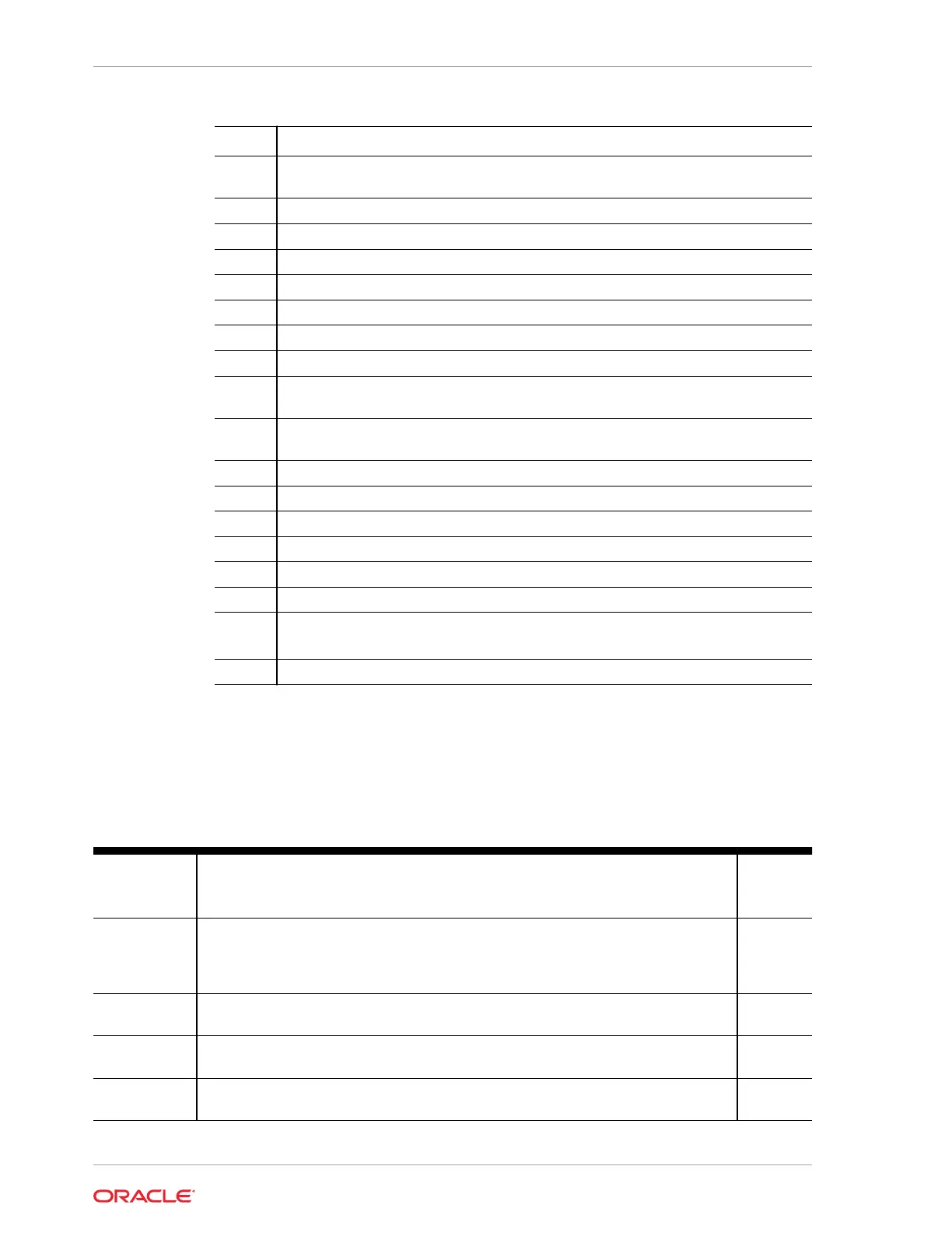
Callout Description
1 Storage drives, up to twelve 3.5-inch hot-pluggable SAS-3 LFF HDDs in 12-Drive
backplane
2 Four storage drive bay cages
3 12-Drive backplane (DBP)
4 System chassis
5 Front LED indicator module and temperature sensor (FIM)
6 Six fan modules (FM0-5)
7 Fan tray
8 Motherboard assembly (MB)
9 Processors (P0, P1) and heatsinks (Single-processor systems contain only a single
processor in socket P0; socket P1 contains a cover to protect processor socket pins.)
10 24 DIMMs (Twelve DIMMs are supported in single-processor systems and the
DIMMs must be installed in P0 DIMM sockets.)
11 Internal M.2 SSD memory with two internal M.2 Risers
12 Top cover
13 Air baffle
14 System RTC battery
15 PCIe card shroud (9-slot PCIe card back panel)
16 (Optional) Oracle RoT card
17 Nine HHHL PCIe cards
PCIe slots 1 through 4 are nonfunctional in single-processor systems.
18 Two power supplies (PS0, PS1)
Replaceable Components
This table lists server replaceable components and provides associated links to
service replacement instructions.
Table 1-1 Replaceable Components
Component
Service
Instructions
Description Service
Level
Storage drives Storage drive configurations can be comprised of NVMe solid state drives (SSDs) or
SAS-3 hard disk drives (HDDs). Configurations may include up to four 2.5-inch hot-
pluggable PCIe-based NVMe SSDs or up to twelve 3.5-inch hot-pluggable SAS-3
HDDs.
Hot
service
Power supplies Two fully redundant AC-powered power supplies. PS0, PS1 Hot
service
Fan modules Six fan modules FM0-5 cool server components. Hot
service
Fan Tray One Fan Tray. See Fan modules Cold
service
Chapter 1
Replaceable Components
1-12