c. Insert and tighten the two No. 2 Phillips screws to secure the LED indicator
module to the server front panel [1].
d. Install the FIM cable cover to the chassis by inserting it into the FIM cable
cover slot [2].
e. Install the three No. 2 Phillips screws to secure the FIM cable cover to the
chassis [2].
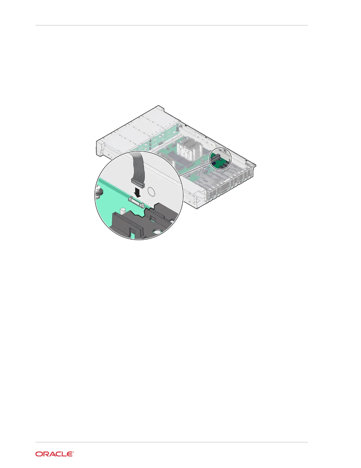
2. Reconnect the LED indicator module cable to the motherboard.
3. Return the server to operation.
a. Install the server top cover.
See Install the Server Top Cover.
b. Return the server to the normal rack position.
See Return the Server to the Normal Rack Position.
c. Reconnect the power cords to the power supplies, and power on the server.
See Reconnect Power and Data Cables and Power On the Server.
d. Verify that the power supply AC OK LED is lit.
Chapter 15
Install the Front LED Indicator Module
15-4