FP2/FP2SHI/O Allocation
3 − 6
3.1 Fundamentals of I/O Allocation
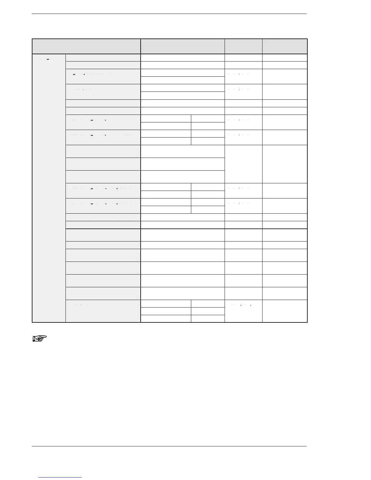
Name Part number Occupied
I/O point
Number of
occupied slot
Intelligent
Analog input unit FP2−AD8VI, FP2−AD8X, FP2−RTD 128SX 1
unit
Analog output unit FP2−DA4 64SY 1
High−speed counter unit FP2−HSCT 32SX, 32SY 1
Pulse I/O unit FP2−PXYT 32SX, 32SY 1
Positioning unit (2-axis type) FP2−PP2 32SX, 32SY 1
Positioning unit (4-axis type) FP2−PP4 64SX, 64SY 1
Positioning unit (Multifunction
Transistor output type FP2−PP21 32SX, 32SY 1
type) 2−axis type
Line driver output type FP2−PP22
Positioning unit (Multifunction
Transistor output type FP2−PP41 64SX, 64SY 1
type) 4−axis type
Line driver output type FP2−PP42
Positioning unit RTEX (2-axis
type)
FP2−PN2AN 128SX, 128SY 1
Positioning unit RTEX (4-axis
type)
FP2−PN4AN
Positioning unit RTEX (8-axis
type)
FP2−PN8AN
Positioning Unit (Interpolation
Transistor output type FP2−PP2T 32SX, 32SY 1
type) 2−axis type
Line driver output type FP2−PP2L
Positioning Unit (Interpolation
Transistor output type FP2−PP4T 64SX, 64SY 1
type) 4−axis type
Line driver output type FP2−PP4L
Multi communication unit FP2−MCU 16SX, 16SY 1
Serial data unit FP2−SDU 16SX, 16SY 1
C.C.U. FP2−CCU 16SE (0SE)
(* Note 3)
1
S-LINK unit FP2−SL2 (* Note 1) 1
Multi-wire link unit FP2−MW 16SE (0SE)
(* Note 3)
1
ET−LAN unit FP2−ET1 32SX, 32SY
(0SE)
1
MEWNET−VE Link unit FP2−VE 32SX, 32SY
(0SE)
1
FNS Unit FP2−FNS 16SE (0SE)
(* Note 3)
1
FMU Unit PROFIBUS FP2−DPV1−M 16SE (0SE)
CAN open FP2−CAN−M
Notes
1) The “occupied I/O point” of S-LINK unit and CPU with S-LINK,
will vary depending on the unit settings. For details, refer to
“FP2 S-LINK Manual”.
2) When using a CPU with S-LINK, the functionality of the slots
are increased, and slot numbers can be allocated as if two S-
LINK units were installed. For more details, refer to “FP2
S-LINK Manual”.
3) The occupied point can be set to “0” with arbitrary allocation.
4) When the handshake by I/O is not used, the number of occu-
pied points can be set to “0” by allocating arbitrarily.