FP2/FP2SHParts and Functions
2 − 8
2.2 FP2 CPU
2.2 FP2 CPU
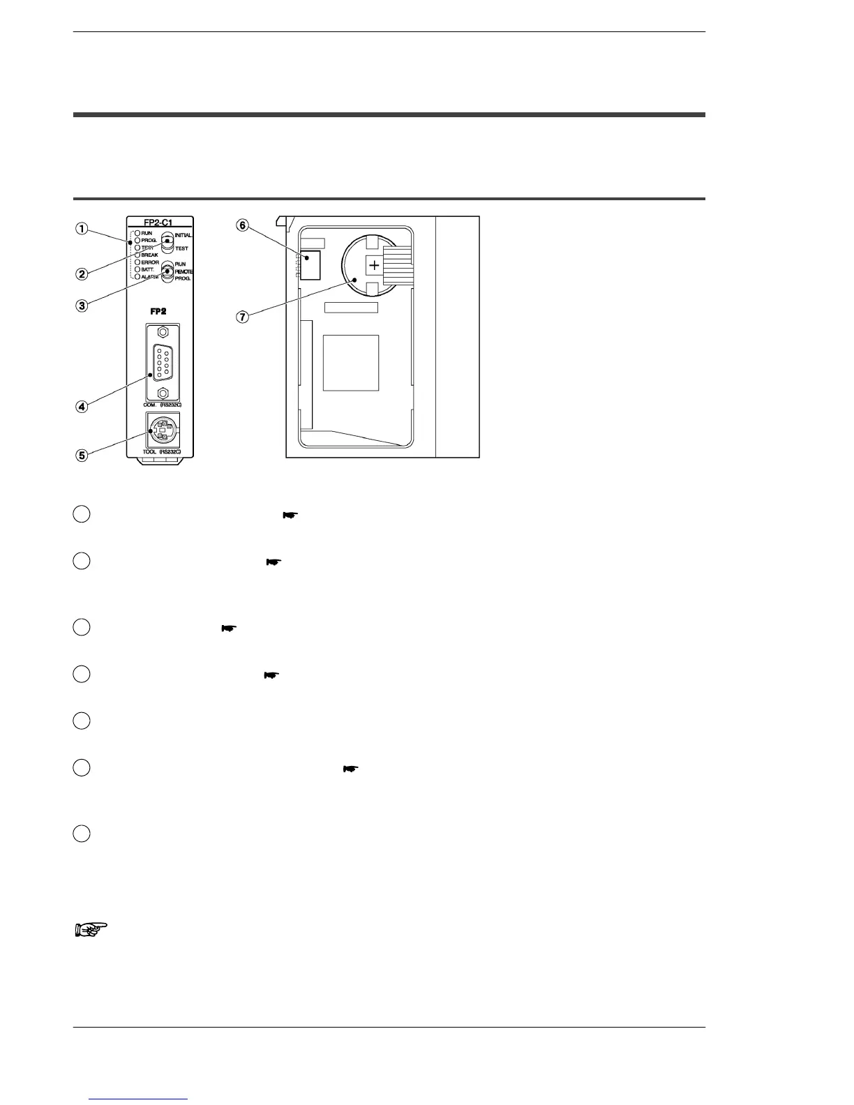
2.2.1 Standard Type CPU (FP2−C1)
Parts Terminology and Functions
1
Status indicator LEDs ( page 2 − 9)
display the operating condition and error statuses.
2
Initialize/test switch ( page 2 − 9)
is used to clear the errors, initializes the operation memory and set the test
operation.
3
Mode selector ( page 2 − 10)
is used to change the operation mode of the PLC.
4
COM port (RS232C) ( page 2 − 11)
is used to connect a computer or general−serial devices.
5
Tool port (RS232C)
is used to connect a programming tool.
6
Operation condition switches ( page 2 − 10)
are used to set the baud rate of the programming tool, to select the program
memory and to select the writing operation for the program memory.
7
Memory backup battery
for backup of the internal memory (RAM).
Part number: AFC8801 (CR2450 or equivalent)
Note
The settings of the operation condition switches become active
when the power is turned on.