FP2/FP2SHInstallation and Wiring
4 − 6
4.1 Installation
4.1.2 Mounting Method
4.1.2.1 Backplane
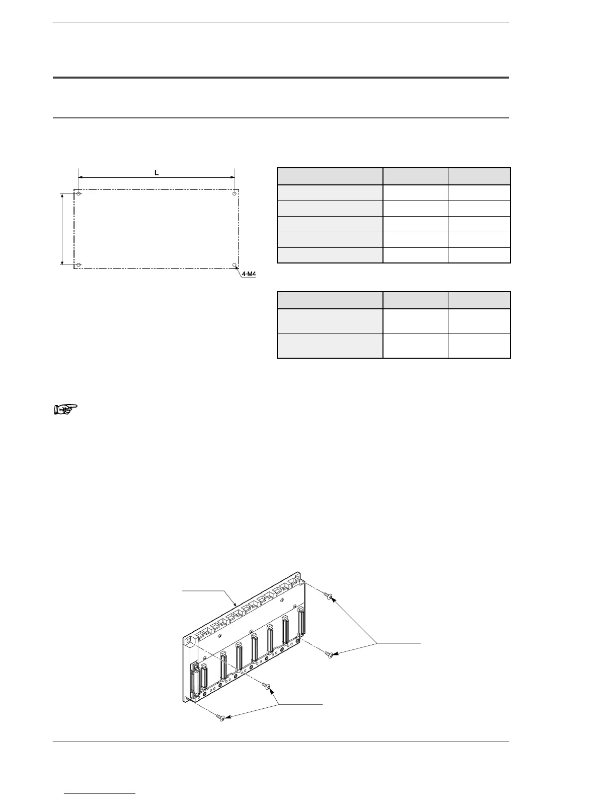
Mounting Hole Dimensions
FP2 backplane
Type of backplane Part number L (mm/in.)
5-module type FP2−BP05 130/5.118
7-module type FP2−BP07 199/7.835
9-module type FP2−BP09 255/10.039
12-module type FP2−BP12 339/13.346
14-module type FP2−BP14 395/15.551
FP2 backplane H type
Type of backplane Part number L (mm/in.)
11-module type
(Basic backplane)
FP2−BP11MH 339/13.346
10-module type
(Expansion backplane)
FP2−BP10EH 339/13.346
Attaching with Screws
Note
Secure the backplane while the unit is not installed.
(Tightening torque: 0.9 to 1.1 N
.
m)
Procedure:
1. Lightly secure the upper part of the backplane using the
mounting holes.
2. Align the mounting holes for the lower part and secure.
3. Tighten the upper screws.
4. Make sure that backplane is securely attached.
M4 screw
M4 screw
Backplane
(Unit mm/in.)
90/3.543