FP2/FP2SHParts and Functions
2 − 30
2.8 Input and Output Units
2.8 Input and Output Units
2.8.1 Common Specifications of Input and Output Units
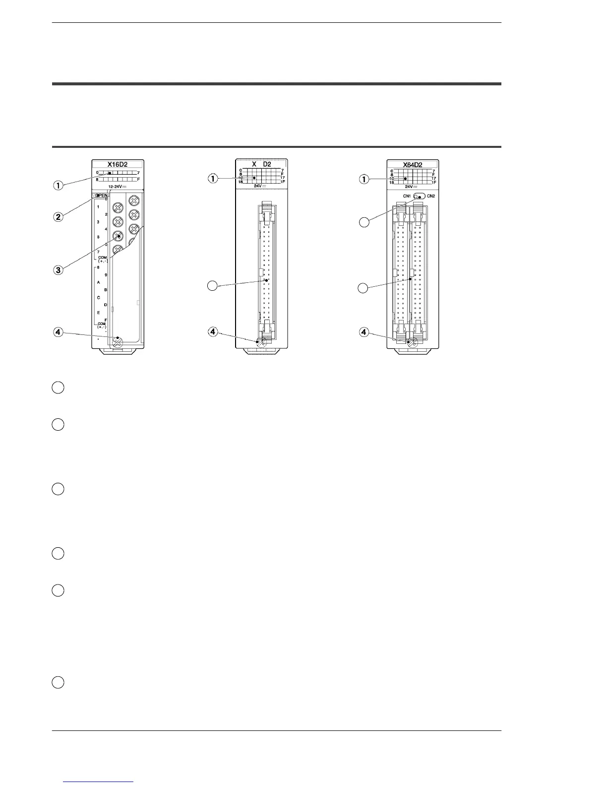
Parts Terminology and Functions
1
Input and output indicators
Indicate the input and output on/off states.
2
Terminal block release lever
By lowering this lever, the terminal block can be removed from the unit without
removing any of the wiring. After installation, push in the lock button at the bottom
of the unit to lock in the terminal block.
3
Terminal block
This is the terminal block for the inputs, outputs, and power supplies. This terminal
block uses M3 sized crimping (pressure connection) terminals. For more information
regarding the crimping (pressure connection) terminals, refer to section 4.5.1.
4
Unit installation screw
Secures the unit to the backplane.
5
Connector
This is the connector for input/output and power supply wiring. This allows the
connector of discrete-wire and the connector of flat cable. For more information
regarding the suitable connectors, refer to section 4.4.1.
For terminal connection, an exclusive cable is available. For more information, refer
to section 4.4.3.
6
Indicator selection switch
Switches between the first 32 points (CN1 position) and second 32 points (CN2
position) of the LED display for the 64-point type unit.
32
5
5
6