Parts and FunctionsFP2/FP2SH
2 − 5
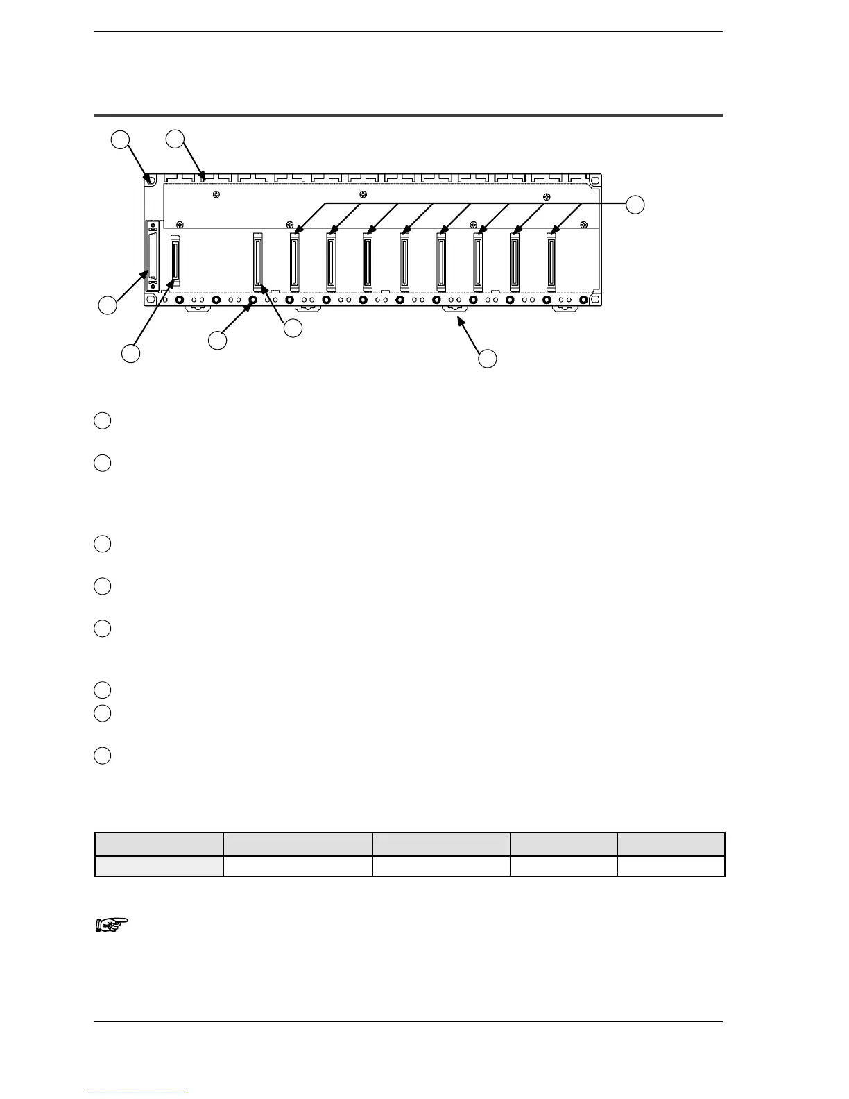
2.1 Backplane and Expansion Cable
2.1.2 Basic Backplane H Type (FP2−BP**MH)
1
2
3
4
8
5
6
7
Parts Terminology and Functions
1
Backplane mounting holes
for mounting the backplane to the control panel. Use M4 screw for the mounting.
2
Unit guides
Align the tab on the unit with this guide when installing the unit to the backplane.
From the left side of the backplane, install the power supply unit, CPU, I/O units,
and intelligent units, in this order.
3
Connector for various units
Install various unit.
4
DIN rail attachment lever
allows attachment to a DIN rail.
5
Unit installation holes
for installing the unit to the backplane. Use the screw supplied with the unit for
installation.
6
Connector for power supply unit
7
Connector for expansion cable
for more details regarding the cable connecting, refer to section 4.1.3.
8
Connector for CPU unit
The position to install the CPU unit is fixed.
Type of Backplane
Type Use Number of module Part number Weight
11-module type Basic system only 11 FP2−BP11MH Approx. 470g
Note
The color of letters on the printed board is yellow to make easier
to distinguish the FP2 backplane H type from the FP2 backplane.