11-62
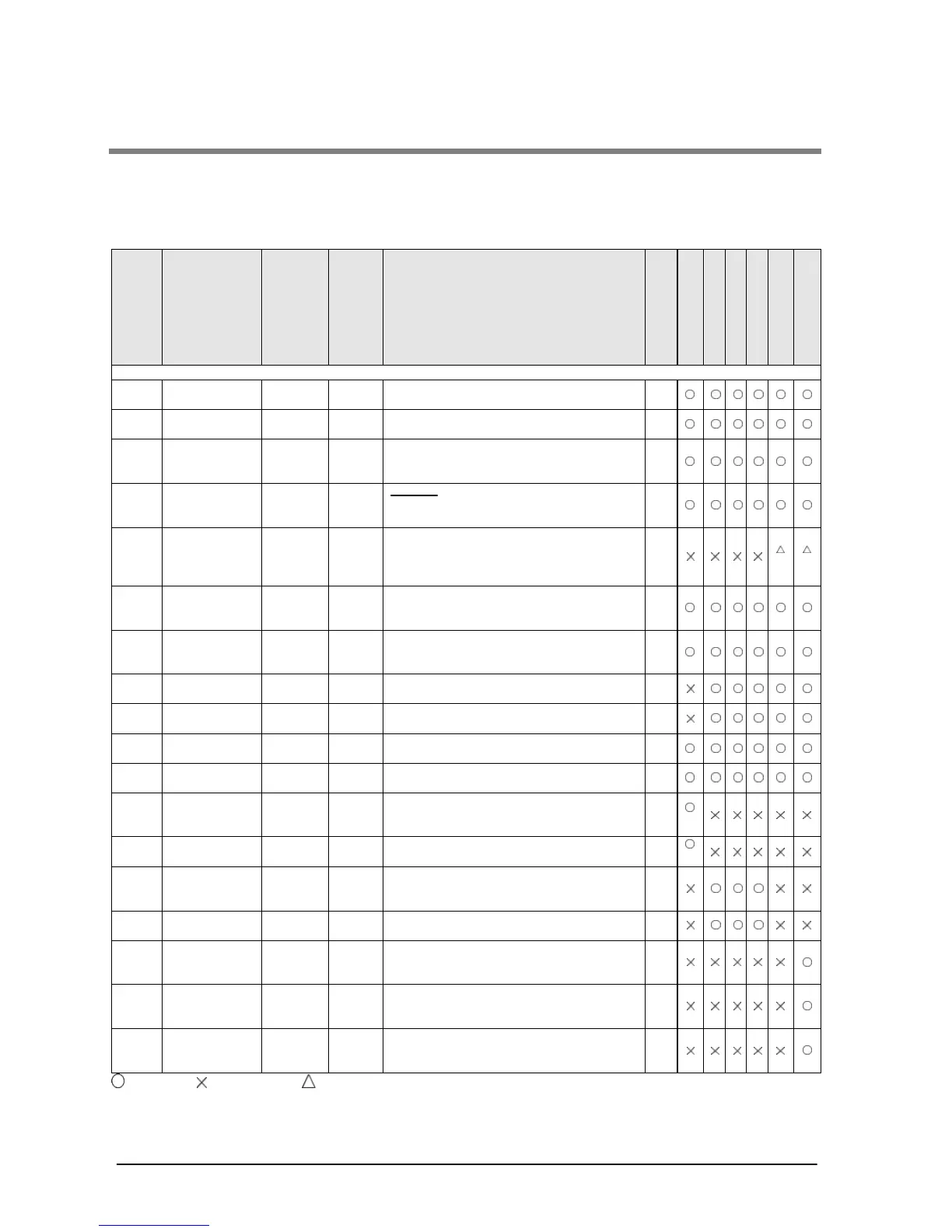
11.3 Table of High-level Instructions
The high-level instructions are expressed by the prefixes “F” or “P” with numbers. For most of the high-level
instructions, “F” and “P” types are available. The differences between the two types are explained as follows:
- Instructions with the prefix “F” are executed in every scan while its trigger is in the on.
- Instructions with the prefix “P” are executed only when the leading edge of its trigger is detected.
For the FP0/FP0R/FPΣ/FP-X, the P type high-level instructions are not available.
Num-
ber
Name
Boo-
lean
Ope-
rand
Description
Steps
FP0/FP-e
FP0R
FP
Data transfer instructions
DMV/
PDMV/
S, D
(S+1, S)→(D+1, D)
7
PGETS
S, D The head word No. of the specified slot is
read.
5
*1 *1
The specified one bit in “S” is transferred to
the specified one bit in “D”. The bit is
The specified one digit in “S” is transferred
to the specified one digit in “D”. The digit is
(S1+1, S1)→(D+1, D),
(S2+1, S2)
The data between “S1” and “S2” is
transferred to the area starting at “D”.
The data of “S” is transferred to the all area
between “D1” and “D2”.
The data stored in the expansion memory
of the EEP-ROM specified by “S1” and “S2”
are transferred to the area starting at “D”.
The data specified by “S1” and “S2” are
transferred to the EEP-ROM starting at “D”.
11
*2
The data stored in the expansion memory
of the F-ROM specified by “S1” and “S2”
are transferred to the area starting at “D”.
11
P13 Data write to
The data specified by “S1” and “S2” are
transferred to the F-ROM starting at “D”.
The data stored in the expansion memory
of the IC card specified by “S1” and “S2”
are transferred to the area starting at “D”.
The data specified by “S1” and “S2” are
transferred to the IC card expansion
memory area starting at “D”.
The program specified using “S” is
transferred into the CPU from IC memory
3
: Available, : Not available, : Not available partially
*1) This instruction is available for FP2/FP2SH Ver. 1.5 or later.FP10SH cannot be used
*2) This instruction is available for FP0 Ver. 2.0 or later and FP-e.