FP2/FP2SHMaintenance
9 − 8
9.2 Preventive Maintenance
9.2 Preventive Maintenance
Although the FP2/FP2SH system has been designed in such a way to minimize mainte-
nance and offer troublefree operation, several maintenance aspects should be taken
into consideration.
If preventive maintenance is performed periodically, you will minimize the possibility of
system malfunctions.
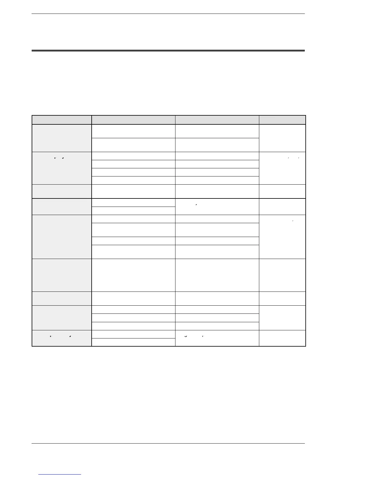
Inspection item Inspection description Basis of judgement Reference
Power supply unit Check POWER LED on power
supply unit
Normal if on Section 2.7
Power supply unit Periodic replacement (20,000
hours of operation)
CPU display Check RUN LED On in RUN state Section 2.2, 2.4,
Check ERROR LED Normal if off
and 8.1
Check ALARM LED Normal if off
Check BATT. LED Normal if off
Input/output unit
display
Check input/output display LED Normal if “light” during on, and
“not light” during off
Section 2.8
Installation condition Backplane mounting looseness Securely mounted Section 4.1.1 and
Looseness and/or play in unit
4.1.2
Connection condition Looseness of terminal screw No looseness Section 4.1.3,
Proximity of connection in pinch
terminal
Pinched parallel
4.2, 4.4 and 4.5
Connector looseness Locked in
Connection condition of expan-
sion cable
Connector section is not loose
Power supply voltage
of power supply unit
Voltage between terminals FP2−PSA1: 100 to 120V AC
FP2−PSA2: 200 to 240V AC
FP2−PSA3: 100 to 240V AC
FP2−PSD2: 24V DC
Section 4.2.1
Power supply voltage
for input/output
Voltage between terminals Within the specified range of each
unit
Section 2.9
to 2.11
Ambient environment Ambient temperature 0to55°C/32 to 131°F Section 4.1.1
Ambient humidity 30 to 85% RH
Operating condition No dust or corrosive gas
Backup battery Battery for CPU Regular replacement Section 9.1.1
Battery for IC memory card