11-54
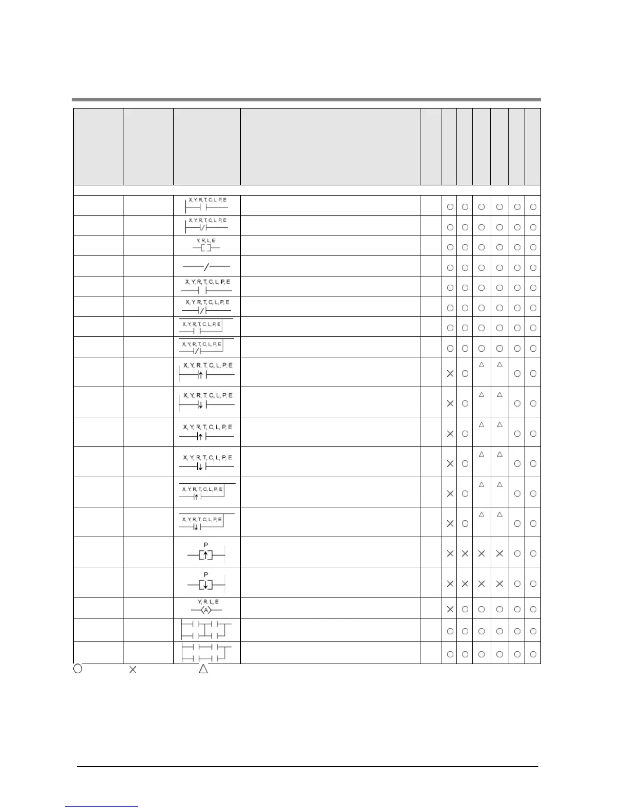
11.2 Table of Basic Instructions
Name Boolean Symbol Description
Steps *3
FP0/FP-e
FP0R
FP
Sequence basic instructions
Begins a logic operation with a Form A
(normally open) contact.
1
(2)
Start Not
Begins a logic operation with a Form B
(normally closed) contact.
1
Outputs the operated result to the specified
output.
1
/
Inverts the operated result up to this
Connects a Form A (normally open) contact
Connects a Form B (normally closed) contact
serially.
Connects a Form A (normally open) contact
in parallel.
Connects a Form B (normally closed) contact
in parallel.
Begins a logic operation only for one scan
when the leading edge of the trigger is
Begins a logic operation only for one scan
when the trailing edge of the trigger is
Connects a Form A (normally open) contact
serially only for one scan when the leading
edge of the trigger is detected.
Connects a Form A (normally open) contact
serially only for one scan when the trailing
edge of the trigger is detected.
Connects a Form A (normally open) contact
in parallel only for one scan when the leading
edge of the trigger is detected.
Connects a Form A (normally open) contact
in parallel only for one scan when the trailing
edge of the trigger is detected.
2
*2
*2
Leading
edge out
Outputs the operated result to the specified
output only for one scan when leading edge
of the trigger is detected. (for pulse relay)
2
Trailing
edge out
Outputs the operated result to the specified
output only for one scan when trailing edge of
the trigger is detected. (for pulse relay)
2
Alterna-
Inverts the output condition (on/off) each time
the leading edge of the trigger is detected.
3
AND
stack
ANS
Connects the multiple instruction blocks
Connects the multiple instruction blocks in
parallel.
1
: Available, : Not available, : Not available partially
*1) The type of the devices that can be specified depends on the models.
*2) This instruction is available for FP-X Ver. 2.0 or later, and FPΣ Ver. 3.10 or later.
*3) In the FP2/FP2SH/10SH, when using X1280, Y1280, R1120 (special internal relay included), L1280, T256, C256 or
anything beyond for the ST, ST/, OT, AN, AN/, OR and OR/ instructions, the number of steps is shown in parentheses.
Also, in the FP2/FP2SH/FP10SH, when a relay number has an index modifier, the number of steps is shown in
parentheses. For the FPΣ and FP-X, the number of steps varies according to the relay number to be used.