11-55
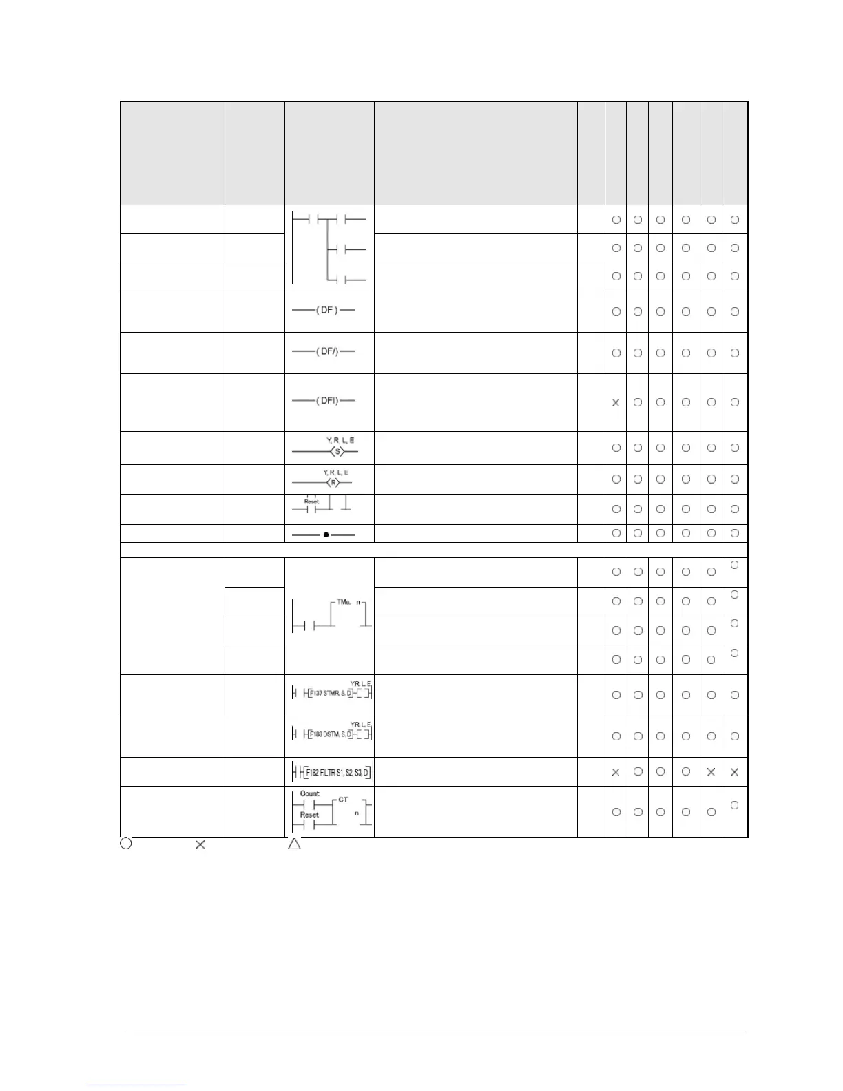
Name Boolean Symbol Description
Steps *5 *6
FP0/FP-e
FP0R
FP
FP-X
FP2
FP2SH/FP10SH
Push stack PSHS
Stores the operated result up to this
instruction. *2
1
Read stack RDS
Reads the operated result stored by
Reads and clears the operated result
stored by the PSHS instruction
1
Leading edge
differential
DF
Turns on the contact for only one
scan when the leading edge of the
Turns on the contact for only one
scan when the trailing edge of the
trigger is detected.
1
Leading edge
differential
(initial execution
DFI
Turns on the contact for only one
scan when the leading edge of the
trigger is detected. The leading edge
detection is possible on the first scan.
1
Output is set to and held at on.
Output is set to and held at off.
3
Keep KP
Outputs at set trigger and holds until
reset trigger turns on.
1
(2)
No operation NOP
No operation.
1
Basic function instructions
After set value “n” x 0.001 seconds,
timer contact “a” is set to on.
3
(4)
*3
TMR
After set value “n” x 0.01 seconds,
timer contact “a” is set to on.
3
(4)
*3
TMX
After set value “n” x 0.1 seconds,
timer contact “a” is set to on.
3
TMY
After set value “n” x 1 second, timer
contact “a” is set to on.
4
(5)
*3
Auxiliary timer
(16-bit)
F137
(STMR)
After set value “S” x 0.01 seconds,
the specified output and R900D are
5
Auxiliary timer
(32-bit)
F183
(DSTM)
After set value “S” x 0.01 seconds,
the specified output and R900D are
Executes the filter processing for the
specified input.
9
Counter
CT
Decrements from the preset value “n”
3
(4)
*3
: Available, : Not available, : Not available partially
*1) The type of the devices that can be specified depends on the models.
*2) The allowable number of using the PSHS and RDS instruction depends on the models.
*3) For FP2SH, FP10SH and FP-X Ver2.0 or later, any device can be set for the setting value of counter or timer instruction.
*4) This instruction is available for FP-X Ver. 2.0 or later.
*5) In the FP2/FP2SH/FP10SH, when using Y1280, R1120 (special internal relay included), L1280 or anything beyond for the
KP instruction, the number of steps is shown in parentheses. Also, in the FP2/FP2SH/FP10SH, when a relay number has
an index modifier, the number of steps is shown in parentheses.
*6) In the FP2/FP2SH/FP10SH, when timer 256 or higher, or counter 255 or lower, is used, the number of steps is the number
in parentheses. Also, in the FP2/FP2SH/FP10SH, when a timer number or counter number has an index modifier, the
number of steps is the number in parentheses. For the FPΣ and FP-X, the number of steps varies according to the
specified timer number or counter number.