FP2/FP2SHParts and Functions
2 − 12
2.2 FP2 CPU
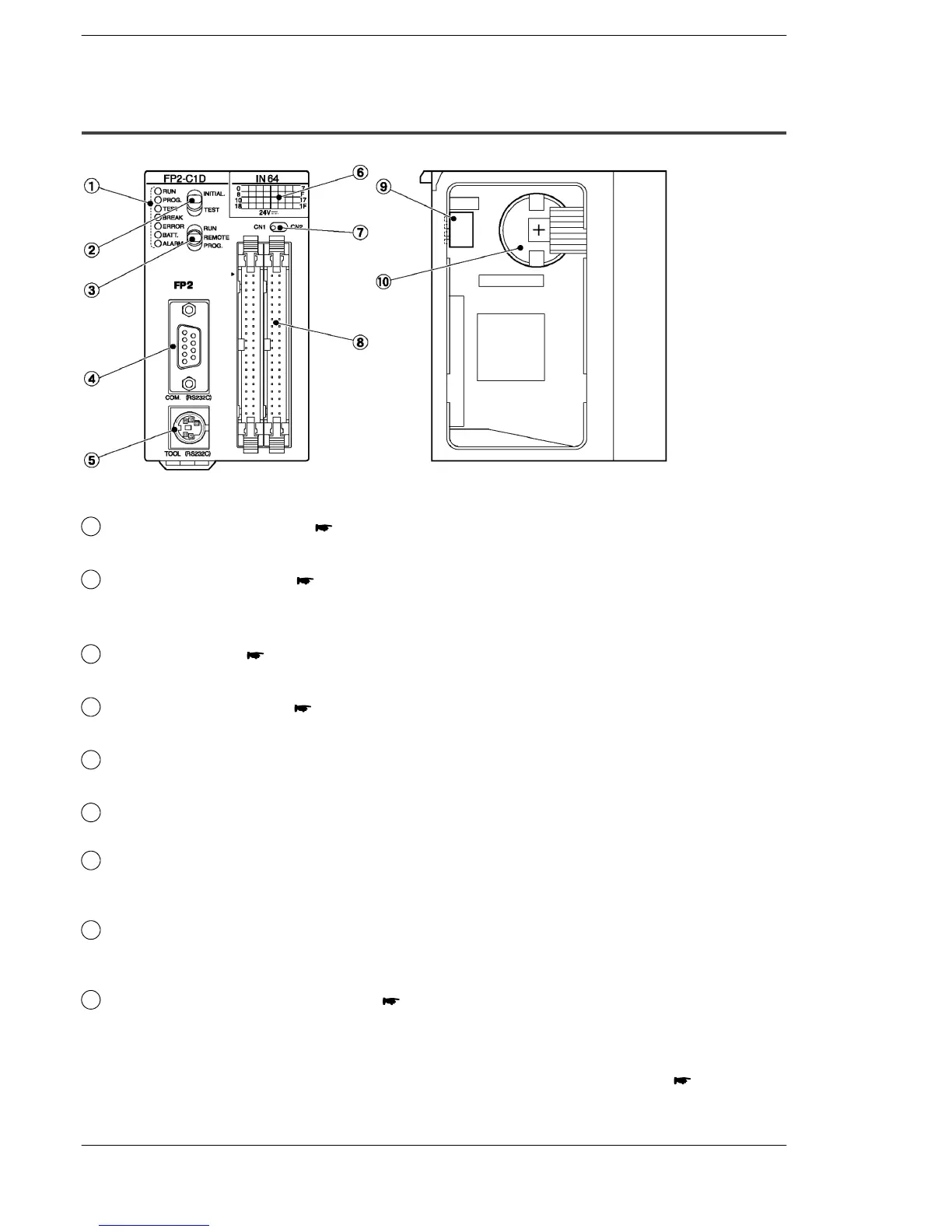
2.2.2 CPU with 64 Points Input (FP2−C1D)
Parts Terminology and Functions
1
Status indicator LEDs ( page 2 − 9)
display the operating condition and error statuses.
2
Initialize/test switch ( page 2 − 9)
is used to clear the errors, initializes the operation memory and set the test
operation.
3
Mode selector ( page 2 − 10)
is used to change the operation mode of the PLC.
4
COM port (RS232C) ( page 2 − 11)
is used to connect a computer or general−serial devices.
5
Tool port (RS232C)
is used to connect a programming tool.
6
Input indicators (32 points)
Indicate the input on/off states.
7
Selector for input indicators
switch between the first 32 points and second 32 points of the 64 points input
LED display.
8
Input connectors
CN1: X0 to X1F
CN2: X20 to X3F
9
Operation condition switches ( page 2 − 10)
are used to set the baud rate of the programming tool, to select the program
memory and to select the writing operation for the program memory.
next page