Installation and WiringFP2/FP2SH
4 − 21
4.3 Wiring Input and Output
4.3.2 Output Wiring
Before the wiring, carefully confirm the specifications for the units to be wired. Specifi-
cally, limitations on the ambient temperature, number of points that can be on
simultaneously and load current will differ for different units.
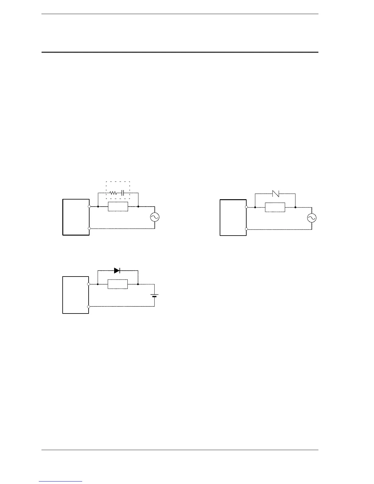
Use a protection circuit when connecting inductive loads and capacitive loads.
Connection of Inductive Loads
When connecting an inductive load, a protective circuit should be connected in parallel
with the load.
When connecting the DC type inductive loads and relay type output unit, be sure to con-
nect a diode for protective circuit across the ends of the load. This will effect the life of
the relay.
When using an AC type inductive load
Output
unit
COM
Output
terminal
Example of surge absorber
(R: 50Ω, C: 0.47µF)
Surge absorber
RC
Varistor
Output
unit
COM
Output
terminal
Load
Load
Diode
When using a DC type inductive load
Output
unit
COM
Output
terminal
Load