FP2/FP2SHParts and Functions
2 − 6
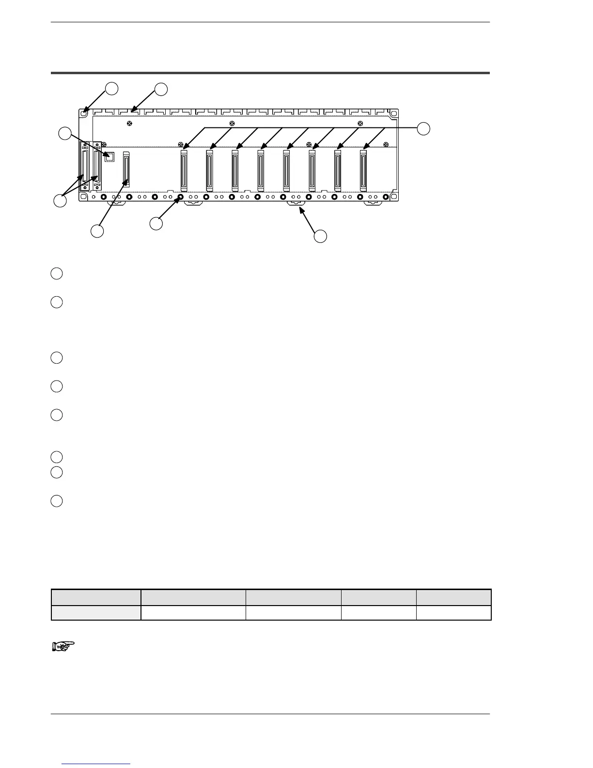
2.1 Backplane and Expansion Cable
2.1.3 Expansion Backplane H Type (FP2−BP**EH)
1
3
4
5
6
7
8
2
Parts Terminology and Functions
1
Backplane mounting holes
for mounting the backplane to the control panel. Use M4 screw for the mounting.
2
Unit guides
Align the tab on the unit with this guide when installing the unit to the backplane.
From the left side of the backplane, install the power supply unit, I/O units, and
intelligent units, in this order.
3
Connector for various units
Install I/O unit.
4
DIN rail attachment lever
allows attachment to a DIN rail.
5
Unit installation holes
for installing the unit to the backplane. Use the screw supplied with the unit for
installation.
6
Connector for power supply unit
7
Connector for expansion cable
for more details regarding the cable connecting, refer to section 4.1.3.
8
Board number setting switch
is used to set a bord number for the expansion backplane. I/O numbers are
assigned according to the board number set the board numbers in increasing
order, 1, 2 and 3 from the board close to the basic backplane.
(Do not set 4 or higher numbers as proper operation cannot be guaranteed).
Type of Backplane
Type Use Number of module Part number Weight
10-module type Expansion system only 10 FP2−BP10EH Approx. 470g
Note
The color of letters on the printed board is yellow to make easier
to distinguish the FP2 backplane H type from the FP2 backplane.