Parts and FunctionsFP2/FP2SH
2 − 3
2.1 Backplane and Expansion Cable
2.1 Backplane and Expansion Cable
2.1.1 Backplane
1 2
3
7
6 5 4
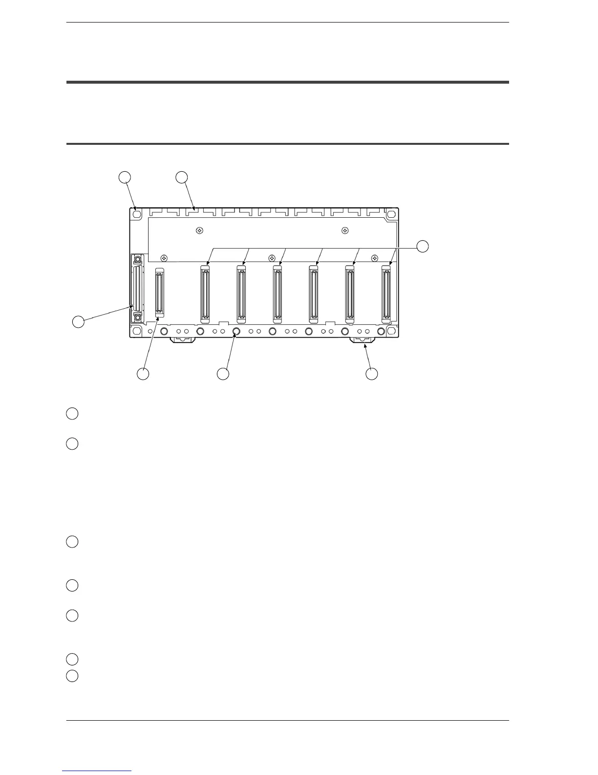
Parts Terminology and Functions
1
Backplane mounting holes
for mounting the backplane to the control panel. Use M4 screw for the mounting.
2
Unit guides
Align the tab on the unit with this guide when installing the unit to the backplane.
For use as the basic backplane (CPU backplane), from the left side of the back-
plane, install the power supply unit, CPU, I/O units, and intelligent units, in this
order.
For use as an expansion backplane, from the left side of the backplane, install
the power supply unit, I/O units, and intelligent units, in this order.
3
Connector for various units
Install a CPU, input, or output unit. When installing a CPU, be sure to install it
next to a power supply unit.
4
DIN rail attachment lever
allows attachment to a DIN rail.
5
Unit installation holes
for installing the unit to the backplane. Use the screw supplied with the unit for
installation.
6
Connector for power supply unit
7
Connector for expansion cable
for more details regarding the cable connecting, refer to section 4.1.3.
This connector is not present on a 5-module type backplane.