I/O AllocationFP2/FP2SH
3 − 15
3.4 Automatic Allocation
3.4 Automatic Allocation
3.4.1 Using Automatic Allocation
After turning on the power, I/O numbers are determined by the I/O unit installation posi-
tions and assigned in order beginning from the left side of the CPU backplane.
If an expansion backplane has been added on the FP2 backplane, the number of slots
for I/O units on the CPU backplane is taken as 16 slots. (The FP2 backplane H type
occupies 8 slots only.)
For a slot with no unit mounted, an equivalent of 16 points (16E) is allocated.
In the case of automatic allocation, I/O numbers are assigned based on the installed
I/O units each time the power is turned on.
Note
With automatic allocation, the contents of allocation are not reg-
istered to the system register.
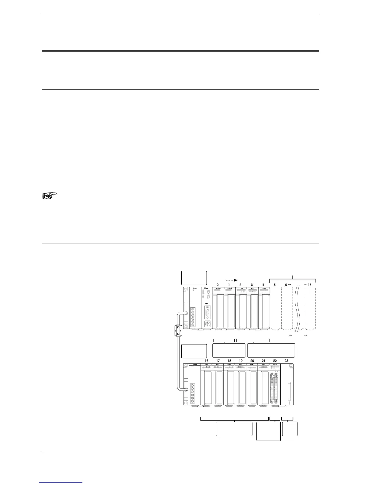
3.4.1.1 Example of Automatic Allocation
The I/O numbers in the illustration are the allocated I/O numbers using automatic alloca-
tion.
CPU backplane
Backplane: 7-module type
Power supply unit: 1 module
CPU: 1 module
I/O units:
16-point type DC input unit: 2 units
16-point type transistor output unit: 3 units
Expansion backplane
Backplane: 9-module type
Power supply unit: 1 module
I/O units:
16-point type relay output unit: 6 units
64-point type DC input unit: 1 unit
CPU
backplane
Expansion
backplane
Slot No.
Slots that do not actually exist
X0
to
XF
Y40
to
Y4F
Y30
to
Y3F
Y20
to
Y2F
X10
to
X1F
Y180
to
Y18F
Y170
to
Y17F
Y160
to
Y16F
Y210
to
Y21F
Y200
to
Y20F
Y190
to
Y19F
X220
to
X25F
50
to
5F
60
to
6F
150
to
15F
260
to
26F
16-point type
DC input unit
16-point type
transistor output unit
Free
slot
64-point
type DC
input unit
16-point type
relay output unit