FP2/FP2SHParts and Functions
2 − 20
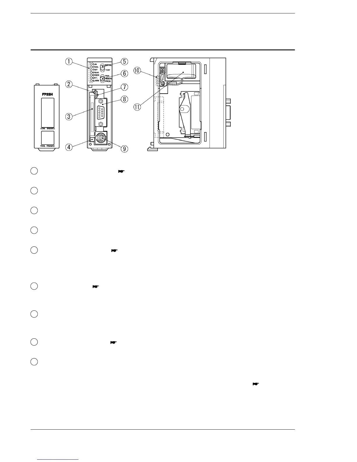
2.4 FP2SH CPU
2.4.2 CPU with IC Memory Card Interface (FP2-C2P/FP2−C3P)
Parts Terminology and Functions
1
Status indicator LEDs ( page 2 − 9)
display the operating condition and error statuses.
2
IC memory card access LED
Illuminates when data is being read from or written to the IC memory card.
3
IC memory card slot
is used when installing an optional IC memory card.
4
IC memory card eject button
Pressing this button ejects the IC memory card.
5
Initialize/test switch ( page 2 − 9)
Setting the switch to the “INITIAL” side clears errors and initializes the operation
memory. Setting the switch to the “TEST” side puts the PLC in the test operation
mode.
6
Mode selector ( page 2 − 10)
is used to change the operation mode of the PLC.
This is used to switch between the RUN, REMOTE, and PROG. modes.
7
IC memory card access enable switch
Setting this switch to the “on” (upward) side enables data to be read and written
to the IC memory card.
8
COM port (RS232C) ( page 2 − 11)
is used to connect a computer or general−serial devices .
9
Tool port (RS232C)
is used to connect a programming tool.
next page