11-30
FP2/FP2SH/FP10SH/FP3 (A: Available, N/A: Not available)
Name Descriptions
Read-
ing
Writ-
ing
FP3
FP2/
FP2SH
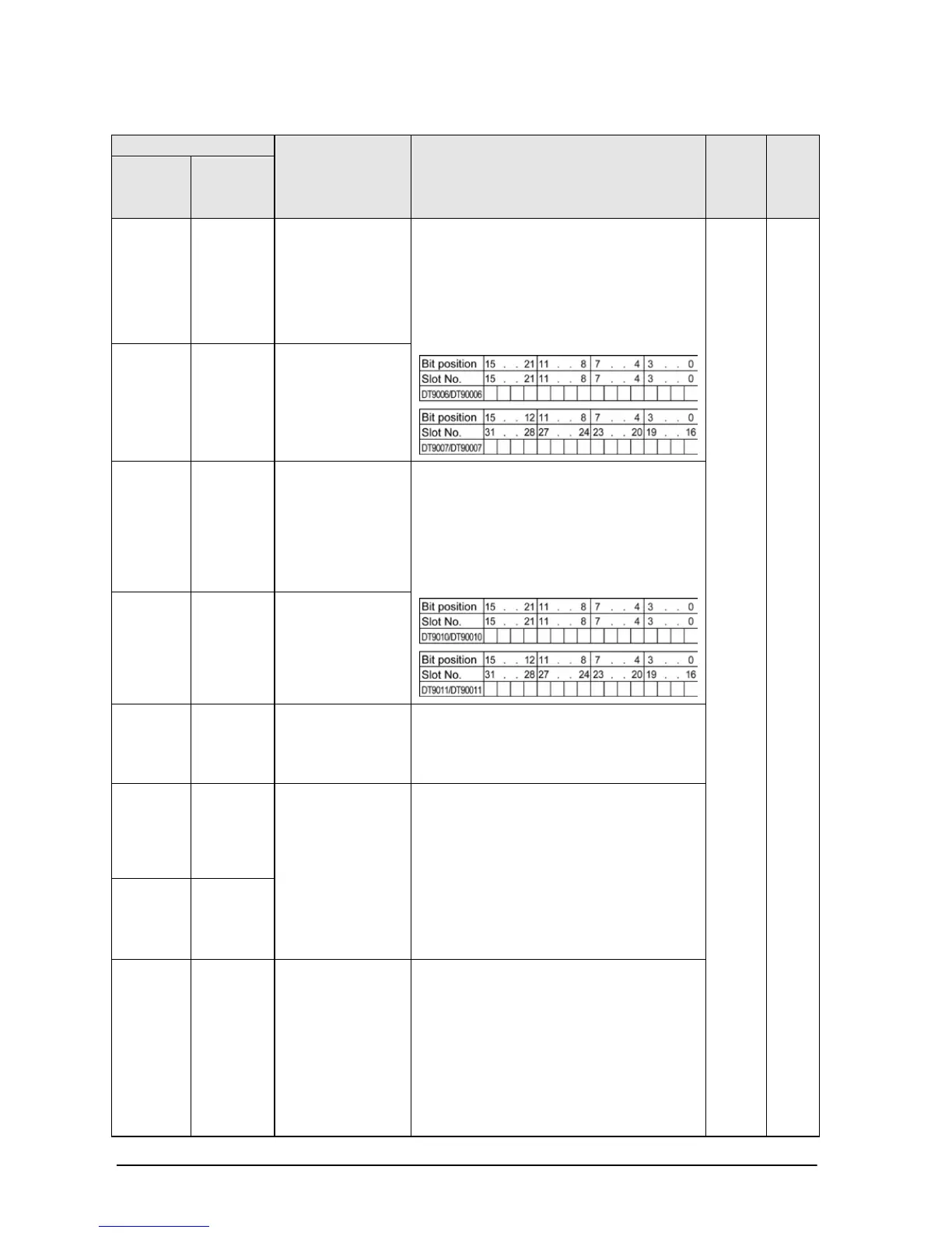
DT9006 DT90006
Abnormal
intelligent unit
(slot No. 0 to 15)
When an error condition is detected in
an intelligent unit, the bit corresponding
to the slot of the unit will be set to on.
Monitor using binary display.
(1: abnormal intelligent unit, 0: normal
intelligent unit)
A N/A
DT9007 DT90007
Abnormal
intelligent unit
(slot No. 16 to
31)
DT9010 DT90010
I/O verify error
unit (slot No. 0
to 15)
When the state of installation of an I/O
unit has changed since the power was
turned on, the bit corresponding to the
slot of the unit will be set to on. Monitor
using binary display.
(1: error, 0: normal)
DT9011 DT90011
I/O verify error
unit (slot No. 16
to 31)
DT9014 DT90014
Auxiliary
register for
operation
One shift-out hexadecimal digit is stored
in bit positions 0 to 3 when F105
(BSR)/P105 (PBSR) or f106 (BSL)/P106
(PBSL) instruction is executed.
DT9015 DT90015
Auxiliary
register for
operation
The divided remainder (16-bit) is stored
in DT9015/DT90015 when F32 (%)/P32
(P%) or F52(B%)/P52 (PB%) instruction
is executed.
The divided remainder (32-bit) is stored
in DT9015 and DT9016/DT90015 and
DT90016 when F33 (D%)/P33 (PD%) or
F53(DB%)/P53 (PDB%) instruction is
DT9016 DT90016
DT9017 DT90017
Operation error
address (hold)
After commencing operation, the
address where the first operation error
occurred is stored. Monitor the address
using decimal display.
FP2SH:
When the higher byte of DT90257 is H2,
the error occurs in the 2nd program
block. In case of the 1st program block, it