PG D
RIVES
T
ECHNOLOGY
O
MNI
– S
PECIFICATIONS
SK78813/5
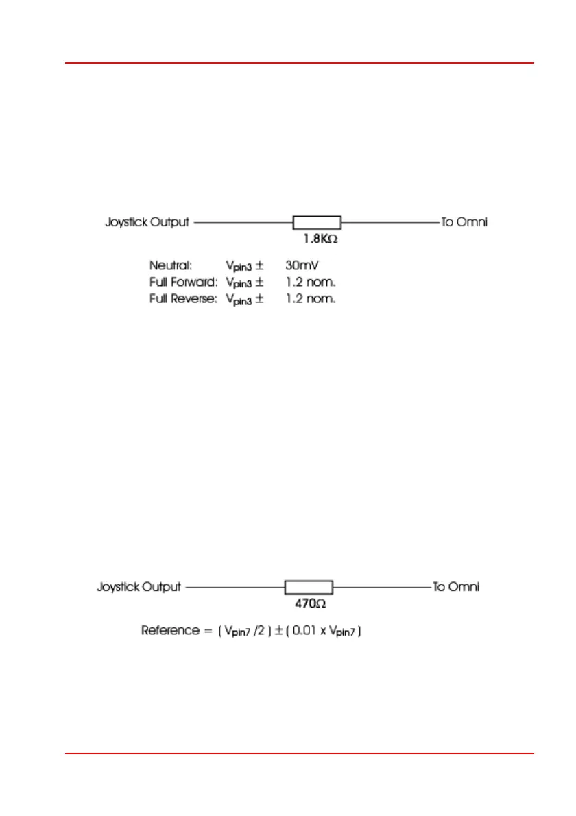
2.2 Pin 2 - Joystick direction
This is the joystick signal which determines the turning component of wheelchair
movement. The joystick has a 1.8KΩ resistor in series with the direction output as
shown below. All voltage levels apply to the actual joystick output, i.e. no load
values. The Omni has an input resistance of 100KΩ to 0V.
For optimum performance, The Omni should be calibrated for individual
joysticks. The voltage swing of 1.2V is a nominal value, actual values of
between 1.1V and 1.3V will be accepted by a calibration sequence.
If the voltage swing with respect to Vpin3 exceeds 3.0V, then the Omni will
assume a fault condition.
2.3 Pin 3 - Joystick reference
This is the joystick center point reference. The joystick has a 470Ω resistor in
series with the reference output as shown below. All voltage levels apply to the
actual joystick output, i.e. no load values. The Omni has an input resistance of
200KΩ to 0V.
 Loading...