PG D
RIVES
T
ECHNOLOGY
O
MNI
– S
TANDARD
- I
NSTALLATION
SK78813/5
The device comprises of three or four direction switches and a User Switch
connected to the Omni via the 9-way D-type connector. In addition, a normally
closed User Switch should be connected to the Omni via the 3.5mm/1/8” jack
socket. This switch, although functionally identical to the switch input on the 9-
way D-type connector, is required to provide a fail-safe emergency stop
system.
8.5 Sip and Puff Device and User Switch
A sip and puff mouthpiece is connected to the Omni via the pneumatic input.
In addition, a User Switch should be connected to the Omni via the 3.5mm/1/8”
jack socket. This switch is required to provide a fail-safe emergency stop
system.
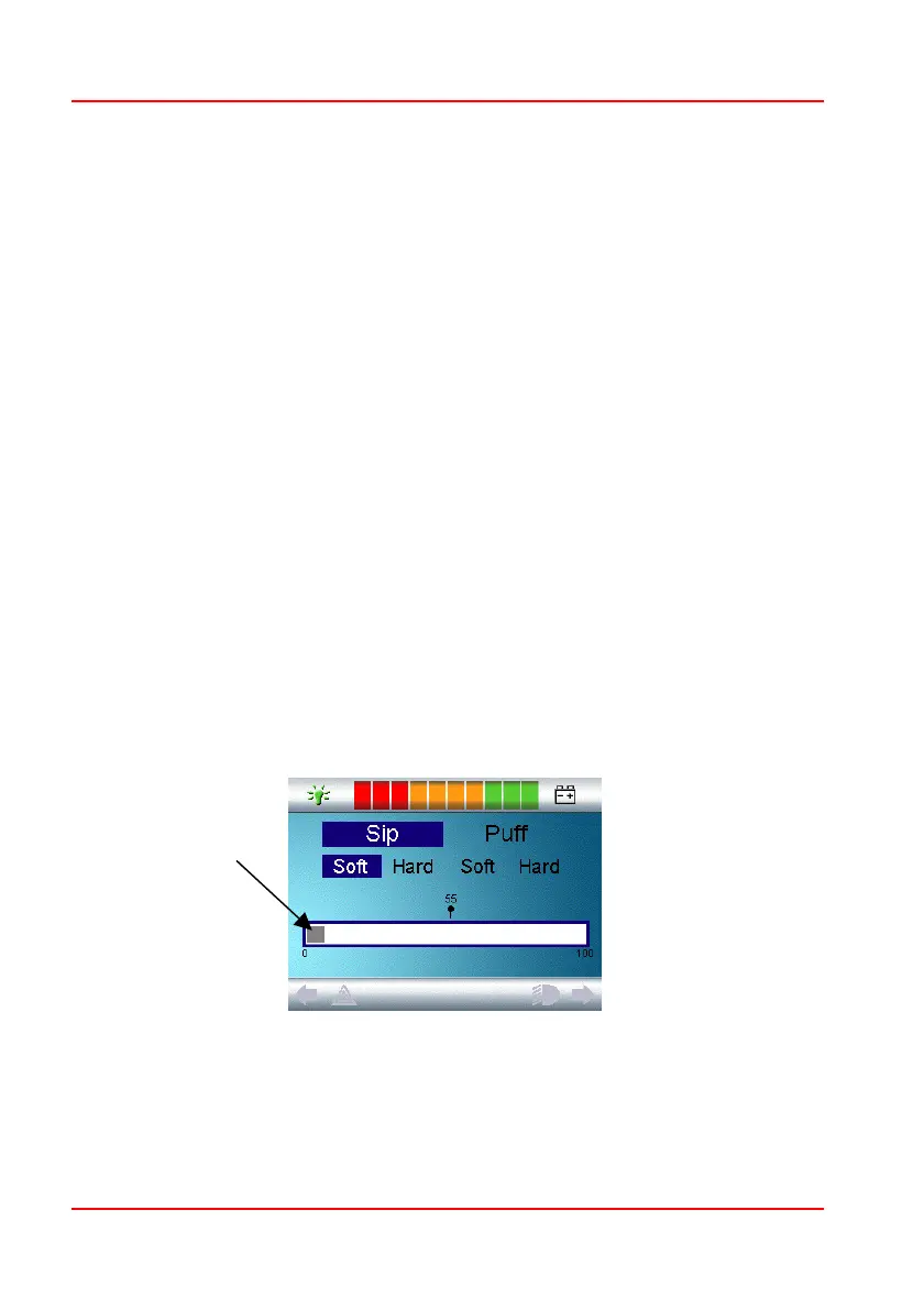
8.5.1 Sip and Puff Calibration
If a new Sip and Puff SID is fitted, then the following calibration procedure must
be performed to match the Omni to the user’s operating capabilities.
To begin the procedure you must first enter OBP mode. From there, follow the
path detailed below, using the right navigation button on the front of the Omni:
Omni – Global – Sip and Puff – Calibrate
A screen like the one shown below should appear.
Soft Sip will be highlighted first. The user must now make a series of soft sips.
After each sip, a live readout of the current pressure will be displayed on the
screen in the form of a line within the 0 - 100 scale. Repeated soft sips will
Deadband
DeadbandDeadband
Deadband
 Loading...