EasyManua.ls Logo

PG Drives Technology R-NET OMNI User Manual

PG Drives Technology R-NET OMNI
174 pages
To Next Page IconTo Next Page
To Previous Page IconTo Previous Page
Page #91 background imageLoading...
Page #91 background image
PG D
RIVES
T
ECHNOLOGY
O
MNI
– S
TANDARD
- P
ROGRAMMING
SK78813/5
91
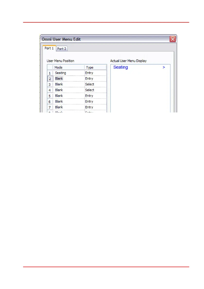
Assume Position 1 = Seating and Position 1 Type = List, then the menu would
appear as below.
Seating 1 >
Seating 2 >
The effect of List is to list all the available Profiles for the Mode. In this case the
two Seating Profiles. The first line denotes the lowest numbered Profile and the
second line the next highest number Profile. In this case Seating Mode in Profile
1 and then Profile 2. The text will be as set by the standard R-net parameter,
Mode Name. Note: although it does in this case, the number does not
necessarily reflect the actual Profile number. Instead Seating 1 would actually
enter the lowest numbered Profile that had Seating Mode enabled, while
Seating 2 would actually enter the next highest numbered Profile. A right SID
command will enter the highlighted Profile.
Assume Position 1 = Seating and Position 1 Type = Select, then the menu item
would appear as below.
Seating < 1 >
The effect of Select is to allow a new Profile to be selected, but not necessarily
entered. Selection is via left and right SID commands. There would be a further
menu item, Seating, that would enter Seating Mode in the selected Profile.

Table of Contents

Question and Answer IconNeed help?

Do you have a question about the PG Drives Technology R-NET OMNI and is the answer not in the manual?

PG Drives Technology R-NET OMNI Specifications

General IconGeneral
CategoryWheelchair
ManufacturerPG Drives Technology
ModelR-NET OMNI
Input Voltage24VDC
DisplayColor LCD
CompatibilityR-NET based power wheelchairs
ConnectivityCAN Bus
Input MethodJoystick, alternative input devices

Summary

Definition of Terms Used and Abbreviations

CHAPTER 1 - INSTALLATION

1 Introduction

Provides an overview of the Omni as a universal specialty controls interface compatible with PG Drives Technology R-net system.

2 Controls and Connections

Details the Omni's physical components, ports, and connections for input devices and power.

3 Installation and Set-up of the Omni

Outlines the suggested sequence for installing and configuring the Omni for powerchair users.

4 Assessing the User’s Needs

Emphasizes the need for healthcare professional assessment of user abilities for SID selection.

5 Installing the Omni onto a Powerchair

Provides guidance on physically mounting the Omni module onto a powerchair using brackets.

6 Installing the SID onto a Powerchair

Details the process of fitting the Specialty Input Device (SID) to the powerchair according to manufacturers' instructions.

CHAPTER 2 - OPERATION

1 General Operating Principles

Explains the Omni's power-up sequence and basic screen display during operation.

2 User Menu

Describes how to access and navigate the User Menu for controlling wheelchair functions via SID or User Switch.

3 Operation with Joystick Type SIDs

Covers operating the wheelchair using joystick-based Specialty Input Devices (SIDs).

4 Operation with Switch Type SIDs

Explains operation using switch-based Specialty Input Devices (SIDs).

5 Operation with 3-axis Proportional and Switch Type SIDs (Head Arrays)

Details operating the wheelchair with head array or similar 3-axis SIDs.

6 Operation with Sip and Puff Type SIDs

Describes how to operate the wheelchair using Sip and Puff input devices.

7 Operation with Single Switch Scanner Type SIDs

Explains operating the wheelchair using a single switch scanner input device.

8 Speed Adjust Mode

Details how to adjust the wheelchair's speed settings via the Omni interface.

9 Lighting Control Mode

Explains how to control vehicle lights and indicators using the Omni.

10 Latched Operation

Describes the functionality and programming for latched operation modes.

11 LCD Screen Details

Provides a comprehensive breakdown of all elements displayed on the Omni's LCD screen.

CHAPTER 3 – PROGRAMMING STANDARD

1 Introduction

Overview of R-net programmable parameters associated with the Omni controller.

1.1 On-Board Programming (OBP)

Details how to program the Omni using its front panel buttons and display.

1.2 Handheld Programming

Explains programming the Omni using the R-net Handheld Programmer.

1.3 PC Programming

Describes how to program the Omni using the R-net PC Programmer software.

2 Details of all Omni Programmable Parameters

Explains the function and effect of all programmable parameters for the Omni.

CHAPTER 4 – PROGRAMMING ADVANCED

1 Introduction

Guidance on advanced programming, recommended for use with an R-net PC Programmer.

2 Using the Omni in Conjunction with a Standard JSM

Details advanced setup for operating Omni with a standard Joystick Module (JSM).

3 Using Omni with Two SIDs

Explains how to connect and configure the Omni for simultaneous use of two Specialty Input Devices (SIDs).

4 Using the Omni with Two SIDs and in Conjunction with a Standard JSM

Covers advanced configuration for Omni with two SIDs and a JSM.

5 Using the Omni by Sound

Describes setting up audible beeps for navigation, useful for users with visual impairments.

CHAPTER 5 – INFA RED CONTROL

1 Introduction

Explains the Omni's IR transmitter/receiver for replicating common IR remote controls.

2 User Menu

Details accessing and using the IR Mode User Menu to control appliances.

3 IR Set Up

Guides through accessing and configuring the IR Set Up menu on the Omni.

4 Learning an IR Code

Step-by-step instructions for teaching the Omni to recognize IR commands from remote controls.

5 Enabling and Disabling IR Codes

Explains how to enable or disable learned IR codes within the Omni's setup.

6 Deleting IR Codes

Provides methods for deleting individual or all learned IR codes from the Omni.

7 IR Configuration Tool

Describes the PC-based application for creating, modifying, and managing IR menus.

CHAPTER 5 – DIAGNOSTICS

1 Introduction

Assists service personnel in identifying probable fault areas within the wheelchair's electrical system.

2 Diagnostic Screens

Explains how diagnostic screens display system trips, identified modules, and trip codes.

3 Diagnostic Text Definitions

Provides definitions for trip texts and their corresponding referral points for troubleshooting.

4 Basic Tests

Recommends essential tests to perform after a repair to ensure system functionality.

CHAPTER 6 – SPECIFICATIONS

1 9-way D Type Pin-out

Details the pin configuration for the 9-way D-type connector used for Specialty Input Devices.

2 Analog Signal Levels

Specifies the voltage levels and resistance for analog joystick signals compatible with the Omni.

3 Digital Signal Levels

Outlines the low/high signal levels and impedance for digital inputs like direction and switches.

4 User Switch

Details the signal levels and configuration for the Omni's User Switch input.

5 On/Off Switch

Describes the signal levels for the Omni's On/Off switch input.

6 Sip and Puff Input

Provides specifications for the pneumatic inlet, including approximate pressure levels.

CHAPTER 7 – WARNING SUMMARY

1 Introduction

Summarizes important warnings for safe installation, maintenance, and operation of the Omni controller.

2 Warnings

Lists critical warnings related to programming, user needs assessment, installation, and usage.

Related product manuals