4: Repair Internal Assemblies — Introduction
90
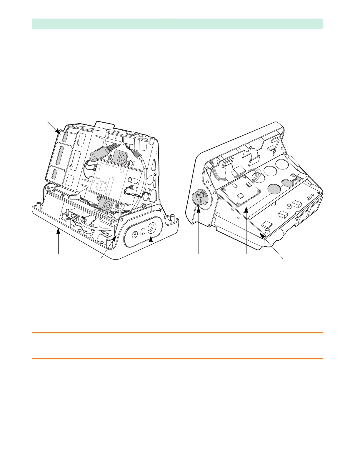
Overview of the Internal Assemblies
The Internal Assemblies are organized in the following groups (see Figure 51):
• Assemblies mounted on the Rear Chassis and Rear Chassis Shelf
• Assemblies mounted on the Front Chassis
• Assemblies mounted directly on the HeartStart XL+ Front Case.
The Rear Chassis may tilt or pivot up or down to provide access to some Front Chassis assemblies
without the removal of the Rear Chassis.
Positioning of the Box
Most of the repairs are performed while the HeartStart XL+ lays with the display side down. Some repairs
are performed while the HeartStart XL+ lays on its bottom or the Capacitor Assembly. See Figure 51.
CAUTION: Never position an open HeartStart XL+ box on its top (shelf) side.
When the Rear Chassis is tilted or not fully secured to the Front Chassis, then the only allowed position
is the “display side down”.
Figure 51 Internal Assemblies Overview
Therapy
Port
Rear Chassis
Shelf
Rear
Chassis
Front Case
Measurement
Module
Display-Side-Down Position Capacitor-Side-Down Position
Front
Chassis
Capacitor
Tray