Internal Assemblies — Rear Chassis 4: Repair
99
Internal Resistors Module
Preparation
1 Open the Case. See “Opening the Case” on page 87.
2 Position the HeartStart XL+ bottom side down, rear side toward you.
3 Remove the Rear Chassis Shelf. See “Rear Chassis Shelf” on page 93.
Removal
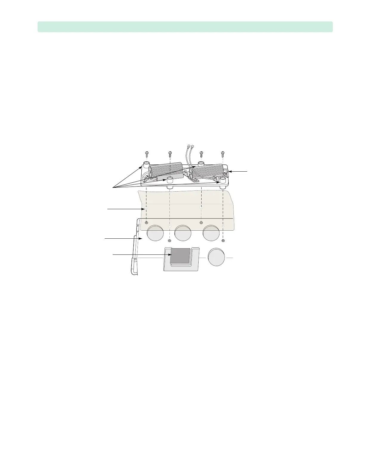
1 Remove the four T10 screws from the plastic standoffs, see Figure 60.
Do not remove the standoffs. Do not detach the resistors from the aluminum mount.
2 Remove the Internal Resistors Module and the two plastic shields.
Replacement
1 Install the Internal Resistors Module and the two plastic shields, see Figure 60.
Position the Internal Resistors Module so that the connectors are toward the foam pad, and the
shield flap is toward the edge.
2 Install the four M3x8 (T10) screws in the plastic standoffs.
3 Tighten the screws to 6 inch-lb (0.7 N m).
4 Install the Rear Chassis Shelf. See “Rear Chassis Shelf” on page 93.
5 Close the Case. See “Closing the Case” on page 151.
To Complete the Replacement:
Run Performance Verification and Safety testing as described in the “Performance Verification”
chapter.
Figure 60 Internal Resistors
Internal
Resistors
assembly
standoffs
two plastic
shields
shelf
foam pad
 Loading...