Internal Assemblies — Front Chassis 4: Repair
149
Display Assembly
Preparation
1 Remove the Printer Assembly. See “Printer Assembly” on page 85.
2 Open and separate the case. See “Opening the Case” on page 87.
3 Remove the Rear Chassis. See “Front Chassis and Case Access” on page 134.
4 Remove the Front Chassis. See “Front Chassis Removal and Replacement” on page 142.
Removal and Replacement
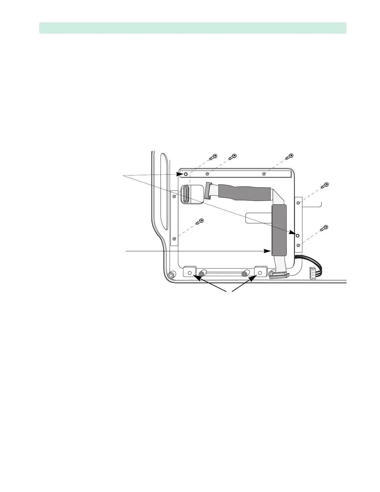
1 Remove the six T15 screws, see Figure 99.
2 Disconnect the Display cable from the Display.
3 Install the Display cable on the new Display.
4 Ensure the connectors are fully seated.
5 Install the new Display on two plastic pins in the Front Case.
– The pins are fragile, take care not to break them.
– Make sure the Inverter PCA cable is not pinched.
– Start the screws manually, then tighten in a criss-cross pattern.
– Tighten the plastite screws to 10 inch-lb. (1.1 N m).
– Do not install screws in the two lower positions!
6 Replace the Front Chassis. See “Front Chassis Removal and Replacement” on page 142.
7 Replace the Rear Chassis. See “Front Chassis and Case Access” on page 134.
8 Close the case. See “Closing the Case” on page 151.
To Complete the Replacement:
1 Run Performance Verification and Safety testing as described in Performance Verification.
2 Run the Display Test, see “Display Test” on page 163.
Figure 101 Display Assembly
plastic pins
Display cable
NO SCREWS HERE