4: Repair Internal Assemblies — Front Chassis
144
Inverter PCA and Front Chassis
Preparation
1 Remove the Printer Assembly. See “Printer Assembly” on page 85.
2 Open and separate the case. See “Opening the Case” on page 87.
3 Remove the Rear Chassis. See “Front Chassis and Case Access” on page 134.
4 Remove the Processor PCA. See “Processor PCA” on page 135.
Removal
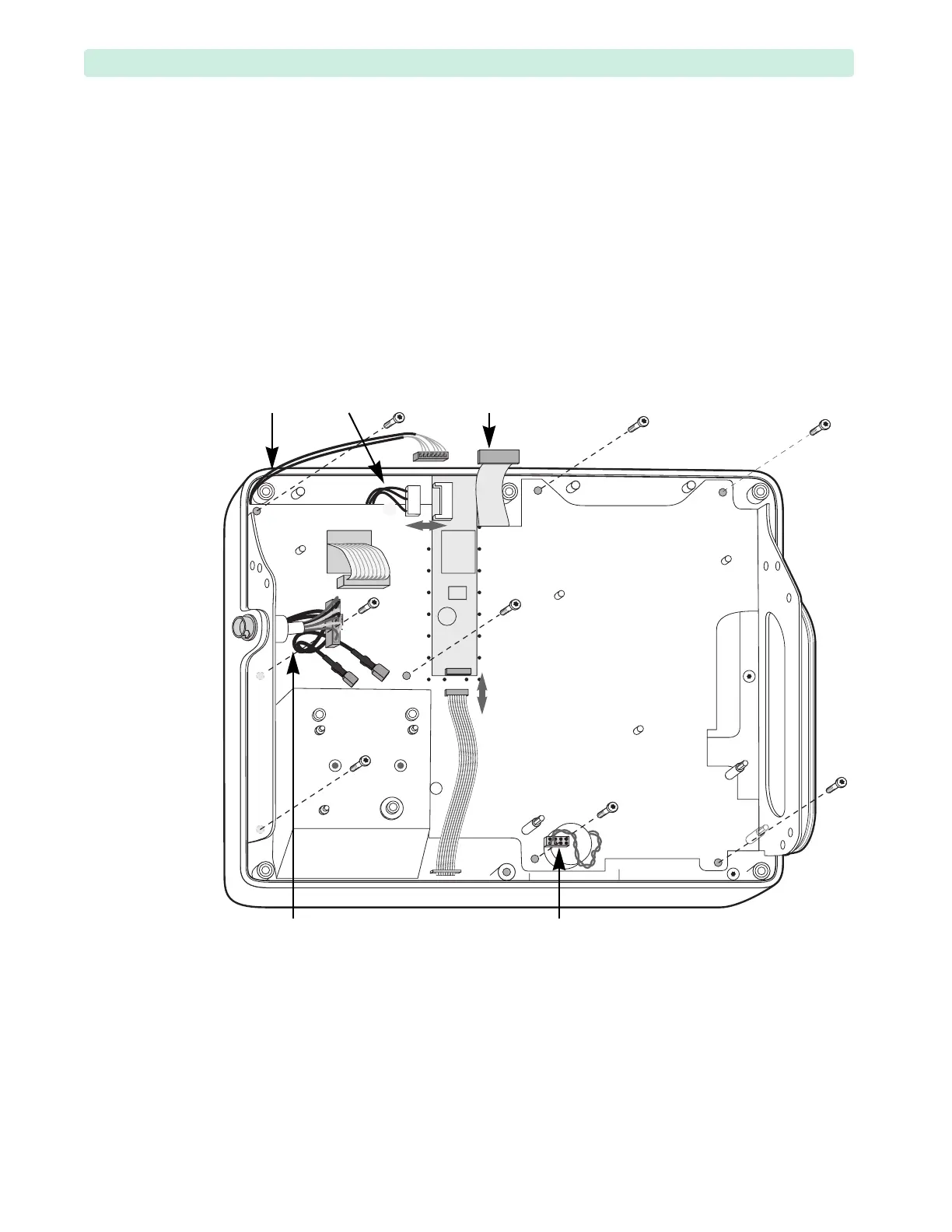
1 Disconnect the Inverter PCA cable
➉, see Figure 97.
2 Remove the screws and the chassis:
a Loosen and remove the six T15 screws
➊ – ➏ as shown in Figure 97.
b Loosen the screws
➐ and ➑ last and leave them in the Front Chassis.
c Move the wires out of the way.
d Lift the Front Chassis straight up.
e Remove the screws
➐ and ➑.
Figure 97 Front Chassis Screws
➊
➋
➌
➍➎
➏
➐
➑
HIF
bundle
Inverter
cable
Display
ribbon cable
Therapy Port
cables
Speaker
bundle
➉