4: Repair Internal Assemblies — Front Chassis
126
SpO
2
PCA
Preparation
1 Open and separate the case. See “Opening the Case” on page 87.
2 Position the device with the display facing down and the printer compartment to your left.
3 Pivot the Rear Chassis upward. See “Pivoting Rear Chassis Upward” on page 122.
Removal
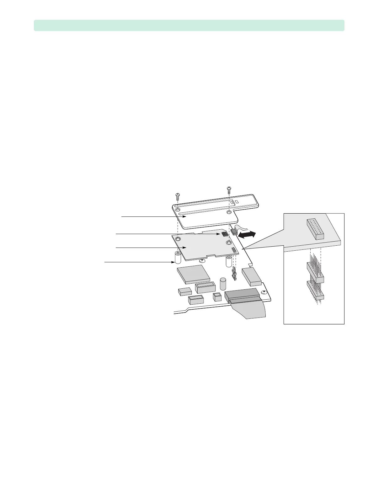
1 Remove the plastic shield, see Figure 81.
a Loosen and remove the two T10 screws.
If the left screw comes out with the nylon standoff underneath, then remove the screw from the
standoff and manually install the standoff back into the Processor PCA. Make sure to not
cross-thread the standoff and torque to no more than 1 inch-lb.
b Lift up the plastic shield.
2 Disconnect the SpO
2
flex circuit from the SpO
2
PCA.
Grasp the connector and pull sideways. Wiggle slightly.
3 Lift the SpO
2
PCA.
As you lift the SpO
2
PCA, it will disconnect from the Processor PCA. The 18-pin stacking
connector may lift up with the SpO
2
PCA or it may stay connected to the Processor PCA. In either
case, keep the connector, because you will need it for the replacement procedure.
Figure 81 SpO
2
PCA Removal
18-pin stacking
connector
plastic shield
flex circuit
SpO
2
PCA
nylon
standoff