4: Repair Internal Assemblies — Front Chassis
134
Front Chassis and Case Access
Remove the Rear Chassis completely to access Front Chassis and Front Case assemblies.
To remove the Rear Chassis:
1 Open the device. See “Opening the Case” on page 87.
2 Disconnect the Rear Chassis:
a Follow the Pivoting Rear Chassis Upward instructions on page 122 up to Step 4.
b Return the Rear Chassis into the upright position and carefully insert four pins in the openings
between the screw holes
➊ and ➋, ➏ and ➐, next to screw ➌, and next to screw ➍.
c Remove the two remaining screws
➊ and ➐.
3 Support the Rear Chassis by the metal frame while removing the pins and put the Rear Chassis aside.
To install the Rear Chassis:
1 Install the Battery PCA screw, see “Battery PCA” on page 116.
Do not attach the Battery PCA connectors.
2 Align the Rear Chassis with the Front Chassis and insert four pins in the openings between the screw
holes
➊ and ➋, ➏ and ➐, next to screw ➌, and next to screw ➍.
3 Insert M3x8 (T10) screws in the screw holes
➊ and ➐.
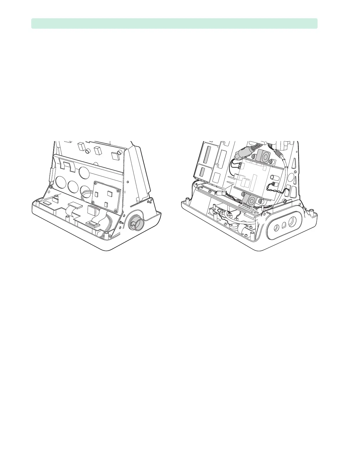
4 Remove the pins and bring the Rear Chassis to the tilted position, see Figure 53 on page 92.
5 Reconnect the cables between the Rear and Front Chassis:
a Reconnect the Battery PCA 4-wire and 3-wire bundles, see Figure 75.
b Reconnect the Network Cable to the Processor PCA, see Figure 78,
➀.
c Reconnect the ECG Out 2-wire bundle to the Processor PCA, see Figure 78,
➁.
d Turn the HeartStart XL+ around and connect the Therapy Port spade connectors, see Figure 69,
➀ and ➁.
e Reconnect the ribbon cable to the Processor PCA, see Figure 69,
➄.
6 If your device has the NBP module, then reconnect the NBP air tube to the NBP Connector, see
“Measurement Module and the Ports” on page 128.
7 Bring the Rear Chassis into the upright position. See “Tilting Rear Chassis” on page 91.
Figure 90 Rear Chassis Removal