Internal Assemblies — Front Chassis 4: Repair
121
Therapy Switch
Preparation
1 Remove the Therapy Knob. See “Therapy Knob” on page 86.
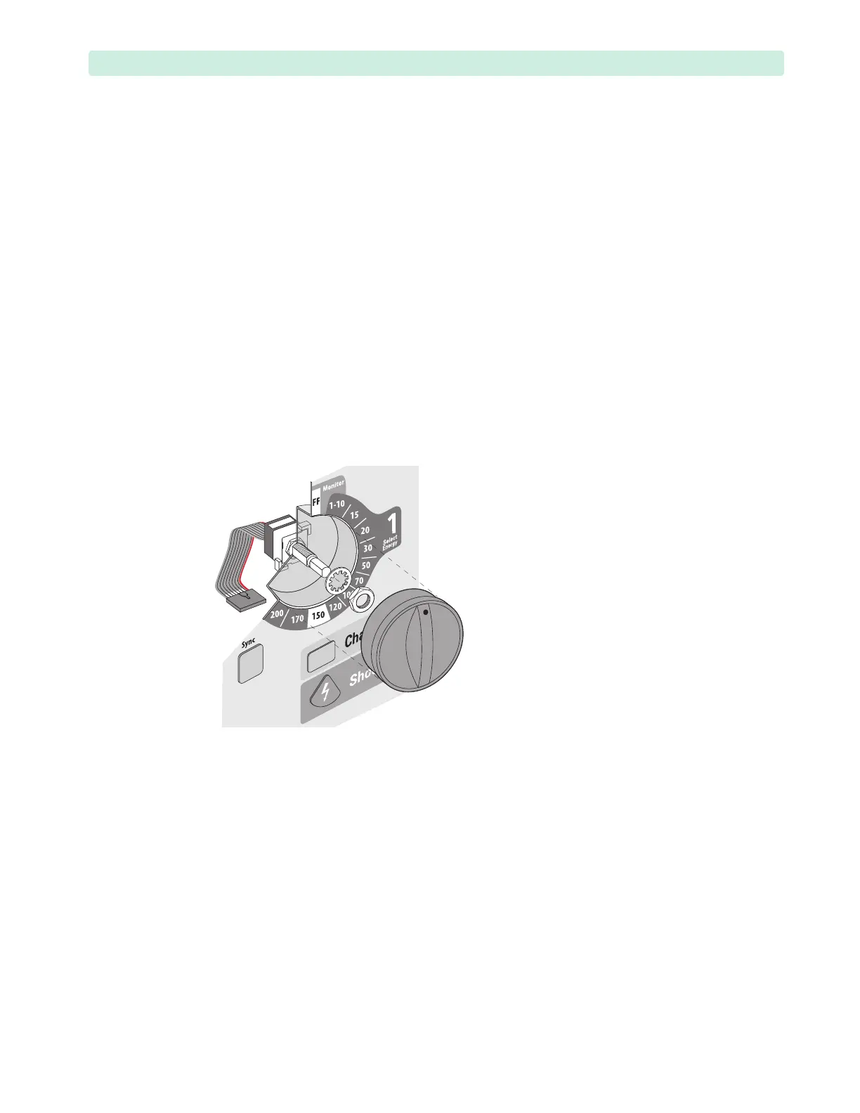
2 Loosen and remove the 9/16-inch nut and washer, see Figure 77.
3 Open and separate the case. See “Opening the Case” on page 87.
4 Position the device with the display facing down and the Measurement Module to your left.
5 Pivot the Rear Chassis downward. See “Pivoting Rear Chassis Downward” on page 108.
Removal
1 Unplug the ribbon cable from the Processor PCA.
2 Remove the Therapy switch.
Replacement
1 Position the switch, as shown in Figure 77.
Position the red stripe on the ribbon cable on the edge closest to the Therapy Port.
2 Connect the ribbon cable to the Processor PCA without twisting or kinking the cable.
Ensure the connector is fully seated.
3 Replace the washer and nut. Tighten the nut to 12 inch-lb. (1.4 N m).
4 Replace the Therapy Knob. See “Therapy Knob” on page 86.
5 Bring the Rear Chassis to normal position. See “Pivoting Rear Chassis Downward” on page 108.
6 Close the case. See “Closing the Case” on page 151.
To Complete the Replacement:
Run Performance Verification and Safety testing as described in the “Performance Verification”
chapter.
Figure 77 Therapy Switch