4: Repair External Assemblies
84
Paddle Tray Load Resistor
The 50-ohm load resistor comes pre-assembled in the paddle tray. However, if it fails, you can replace it
using the following procedures.
Preparation
1 Turn the device off and remove the battery and the AC power.
2 Remove the Handle Assembly, see “Handle Assembly” on page 78.
3 Remove the paddle tray. See “Paddle Tray and Plates” on page 81.
Do not remove the plates.
Removal
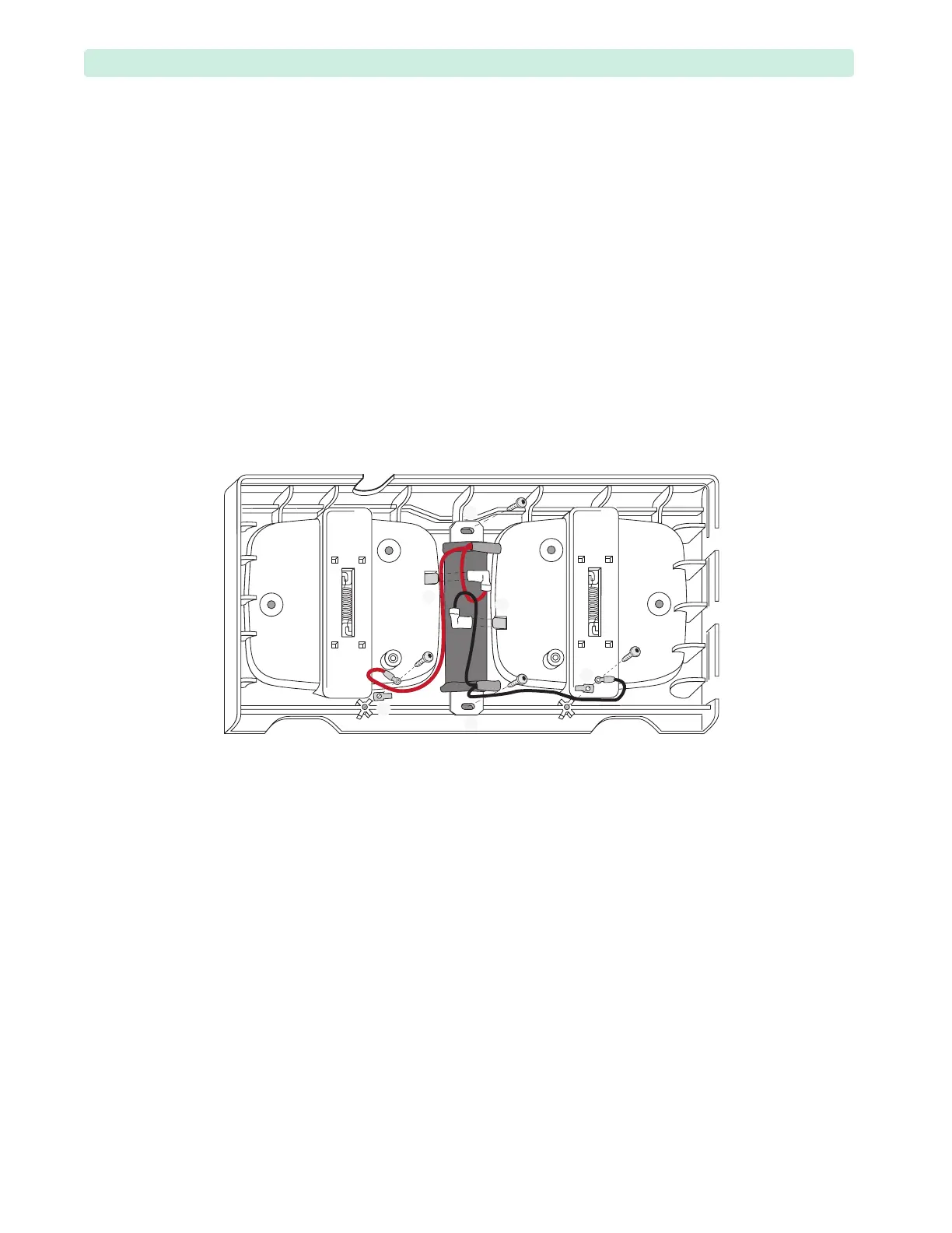
1 Disconnect the spade connectors from the paddle plate tabs (
➊, ➋).
2 Remove the four T15 screws (
➌, ➍). Put aside the two spade connectors.
3 Lift the 50-ohm load resistor and the wires out of the paddle tray.
Replacement
1 Place the load resistor into the paddle tray. Position the wires and connectors as shown in Figure 45.
Secure with two T15 plastite screws (
➌).
2 Place two other T15 plastite screws through the spade connectors and ring terminals, and secure to
the paddle tray on both sides (
➍). Tighten the four screws to 10 inch-lb. (1.1 N m).
3 Connect the spade connector from the red wire to the left plate tab (
➊) being careful not to bend
the tab. The tab is marked RED.
4 Connect the spade connector from the black wire to the right plate tab marked BLACK (
➋).
5 Ensure the connectors are fully seated.
6 Route the wires as shown in Figure 43 on page 81.
7 Replace the paddle tray, see “Paddle Tray and Plates” on page 81.
To Complete the Replacement:
Run Performance Verification and Safety testing as described in the “Performance Verification”
chapter.
Figure 45 Replacing the Load Resistor