Chapter 3 Calibration
Revision W HF Series X-ray Generators - Service Manual
3-34 Quantum Medical Imaging, LLC
A/D Calibration
The A/D (analog/digital converter) calibration utility is used to adjust and cal-
ibrate specific operating voltages within the x-ray generator against a trace-
able calibrated voltage measurement instrument, such as a DMM. Once A/D
calibration has been performed, the A/D calibration utility may then be used
as a diagnostic tool allowing the technician to "read" these voltage measure-
ments without having to remove the cover from the generator cabinet and
without connecting a meter.
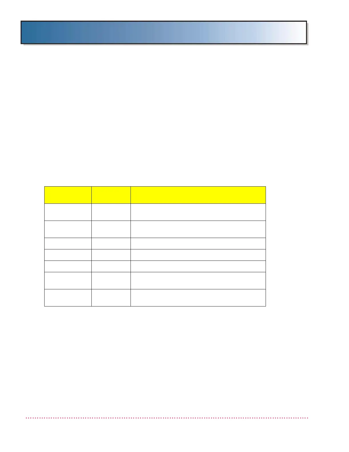
Table 3-5 shows the various voltage levels (with tolerances) that can be
adjusted and calibrated using this utility, and it provides the location of the
test point to which a calibrated voltmeter must be connected for measuring
the actual voltage level:
The following procedure adjusts and calibrates the generator to verify accu-
rate system measurement of selected operating voltages. The same proce-
dure applies to any of the voltage levels available for selection. Voltage
measurement accuracy is verified using your pre-calibrated voltmeter (trace-
able to NIST standard) as the benchmark. Once calibrated, the generator’s
CPU continuously monitors these internal voltages and will terminate or not
allow exposure if certain tolerances are exceeded.
Table 3-5. A/D Calibration Voltages
Voltage Level
Calibration
Accuracy
Test Point Measurement Location
+400V Cathode ±8 VDC
+/- bus bars on Capacitor Bank next to Power Mod-
ule A19 (left side looking into generator cabinet)
+400V Anode ±8 VDC
+/- bus bars on Capacitor Bank next to Power Mod-
ule A18 (right side looking into generator cabinet)
+5VDC ±0.1 VDC TP1 on Logic Board AY40-006S
+15VDC ±0.2 VDC TP3 on KVP Control Board AY40-003S
-15VDC ±0.2 VDC TP5 on KVP Control Board AY40-003S
+24VDC ±0.3 VDC
TP8 on Power Supply Board
AY40-005T
+24V Brake ±0.3 VDC
Terminal TB2-1 on Interface Board AY40-023T (or
AY40-034T)
 Loading...