Chapter 2 Assembly & Installation
HF Series X-ray Generators - Service Manual Revision W
Quantum Medical Imaging 2-15
High Voltage (H.V.) Tank
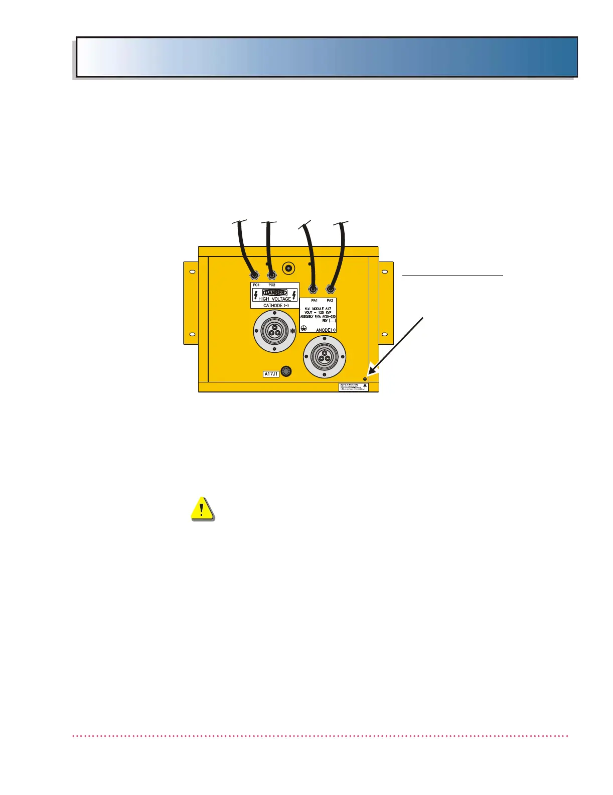
The HF Series X-ray Generator is shipped with the H.V. Tank installed at the
factory. Locate the Pressure Relief Screw on the top side of the H.V. Tank near
the front right corner (see Figure 2-10). To permit venting, loosen screw two
(2) turns (counterclockwise) and leave in this position.
Figure 2-10. H.V. Tank (Top View)
The following instructions are provided should it be necessary to install the
H.V. Tank. When installing the H.V. Tank, keep it upright at all times. See
Figure 2-11 and proceed as follows:
WARNING! After completing the following proce-
dure, double-check the H.V. Tank wiring connec-
tions to make sure they are correctly connected.
Incorrect wiring can cause damage to the genera-
tor. Ensure that ground wires are connected.
HV TANK (TOP VIEW)
PRESSURE RELIEF SCREW:
AT TIME OF INSTALLATION,
TURN SCREW COUNTER-
CLOCKWISE TWO (2) TURNS
AND LEAVE IN THIS
POSITION.
 Loading...