Appendix B Calibration (DiRex System)
HF Series X-ray Generators - Service Manual Revision W
Quantum Medical Imaging, LLC B-55
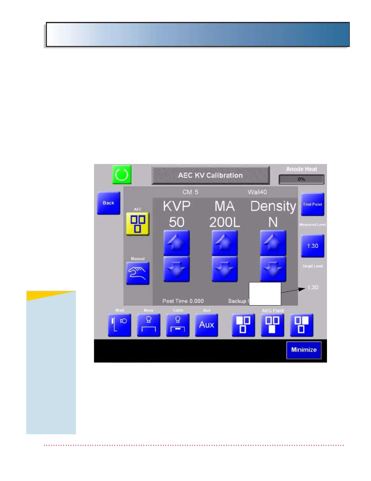
AEC KV Calibration Procedure
The AEC KV Calibration screen (shown below) is used to calibrate the tube
voltage to the "Target Level" density setting. There are a total of six kV cali-
bration points for a 125 kV system (50, 60, 80, 100, 110, and 120 kV); 150 kV
systems require an additional two kV calibration points (130 and 140 kV).
The image receptor and chamber field settings remain the same as those
used in the AEC Optical Density Calibration procedure.
1. Access the AEC KV Calibration Screen (shown below) and proceed as fol-
lows.
Figure B-28. AEC KV Calibration Screen
2. Place indicated thickness of acrylic (5 CM for first calibration point) in the
X-ray beam.
3. Insert a CR Film Plate and collimate down to film size.
4. Take an exposure at the setting indicated in the AEC KV Calibration
Screen (i.e., 50 kVp, 200L mA, normal density).
NOTE
Calibration of the
first step (50 kVp)
is not required as
long as AEC
Optical Density
Calibration
procedure in the
previous steps
was performed
prior to AEC KV
Calibration. A
verification that
the "Measured
LGM" is the same
as the "Target
Level" setting is
all that is
required.
 Loading...