Chapter 2 Assembly & Installation
HF Series X-ray Generators - Service Manual Revision W
Quantum Medical Imaging 2-47
upgrade kits are available (contact Quantum Technical Support for more
information).
Refer to the Integration System Service Manual provided, depending on the
the type system integration, for system interconnection and software installa-
tion instructions. A general Q-Connect Option System Interconnection Dia-
gram is provided in Chapter 6, DIAGRAMS in this manual for reference.
Optional Remote Expose Switch Connection
This option is not applicable on generators equipped with Q-Con-
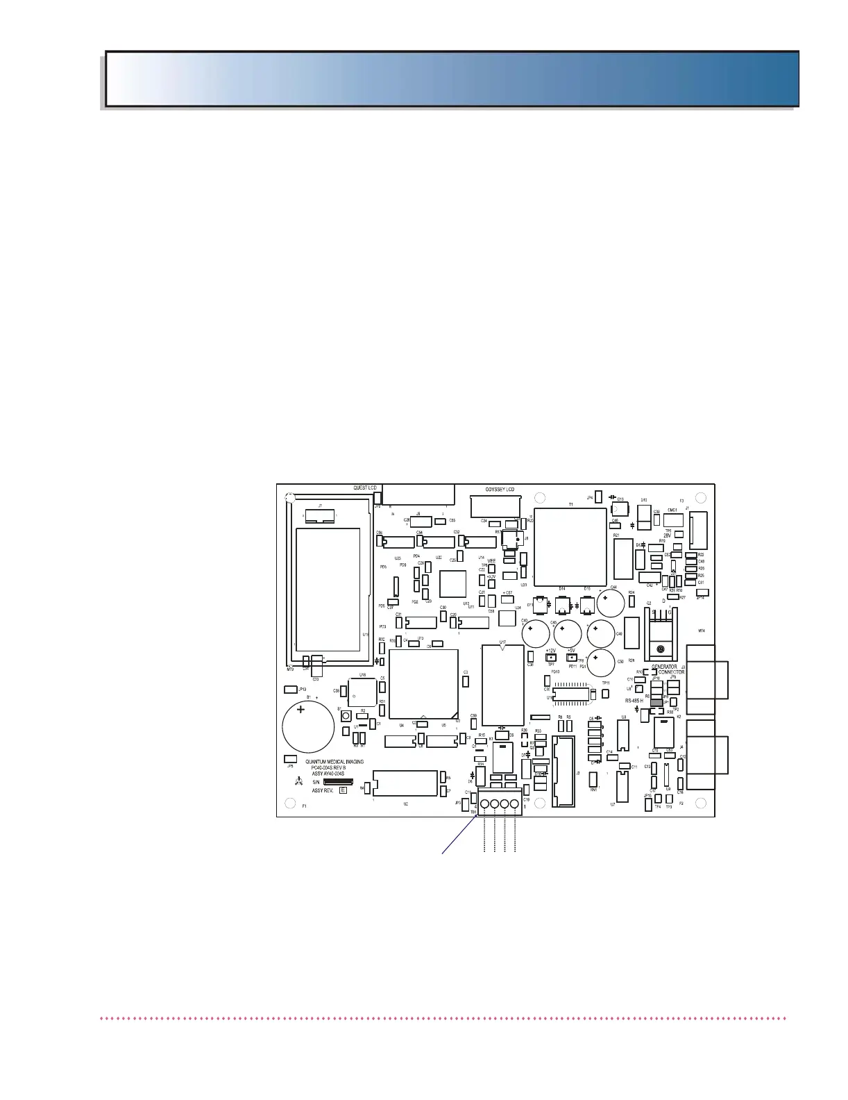
nect option. Optional remote expose switch (R80-HS) is wired into the OCP
Board A16A1 (P/N AY40-004S) at TB1 as shown in Figure 2-25, below. If
desired, removing jumpers JP6 and JP7 on OCP Control Board A16A1 (AY40-
004S1) disables the operation of the PREP and EXPOSE buttons on the oper-
ator control panel (see figure below).
Figure 2-25. Operator Control Panel (OCP) Control Board Terminal Block TB1
Connections for Remote Expose Switch
INITIAL POWER UP
With the generator completely assembled and when electrical checks are com-
plete, the system is ready for initial power up. Proceed as follows:
DANGER HIGH VOLTAGE
RESET
11
1
10
20
1
1
1
1
1
1
RS-232
1
4
1
TP10
R23
D19
JP11 C43
R18
C41
JP12
U10
C27
U19
R35
R34
TP9
JP7
R13
R12
JP6
JP16
R11
R16
TP1
D16
PD6 PD7
R37
D2
D4
D3
TB1
P
R
E
P
E
X
P
O
S
E
C
O
M
M
G
N
D
 Loading...