Chapter 5 Service Instructions
HF Series X-ray Generators - Service Manual Revision W
Quantum Medical Imaging, LLC
5-75
Power Modules A18 and A19 (P/N AY20-047) Removal
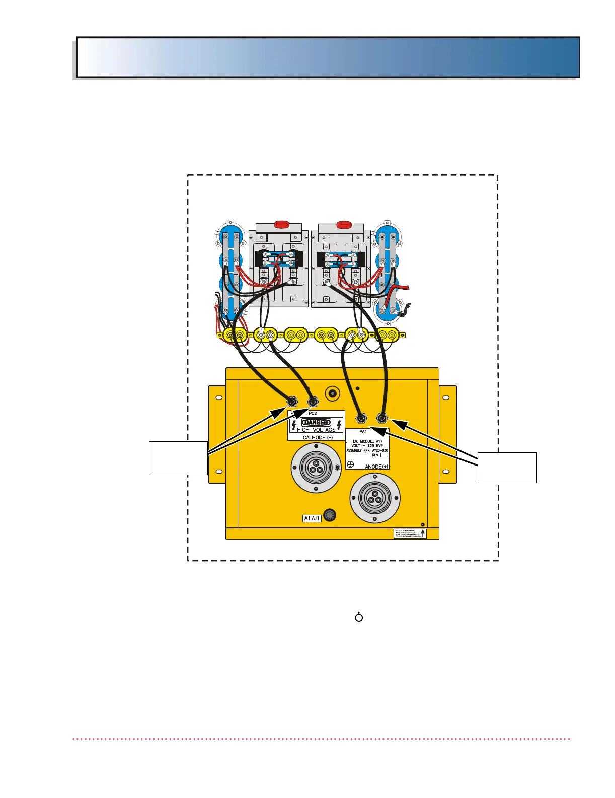
Figure 5-6. Power Module A18 and A19 Cable Connections
1. Set the power on/standby switch on the Operator Control Panel
(OCP) to the standby ( ) position.
2. Set the ON/OFF circuit breaker CB1 on the generator cabinet to
OFF position.
3. Loosen nine (9) screws that secure the Generator Cabinet Cover
to the Generator Chassis.
*C5
C4C3
C6
*C8
C7
POWER
MODULE A19
POWER
MODULE A18
GENERATORS
H.V. TANK (TOP VIEW)
TERMINALS
PC1, PC2
TERMINALS
PA1, PA2
 Loading...