Chapter 2 Assembly & Installation
HF Series X-ray Generators - Service Manual Revision W
Quantum Medical Imaging 2-35
(Note: Perform ion chamber balance procedure in accordance with manufac-
turer’s instructions provided with chamber.)
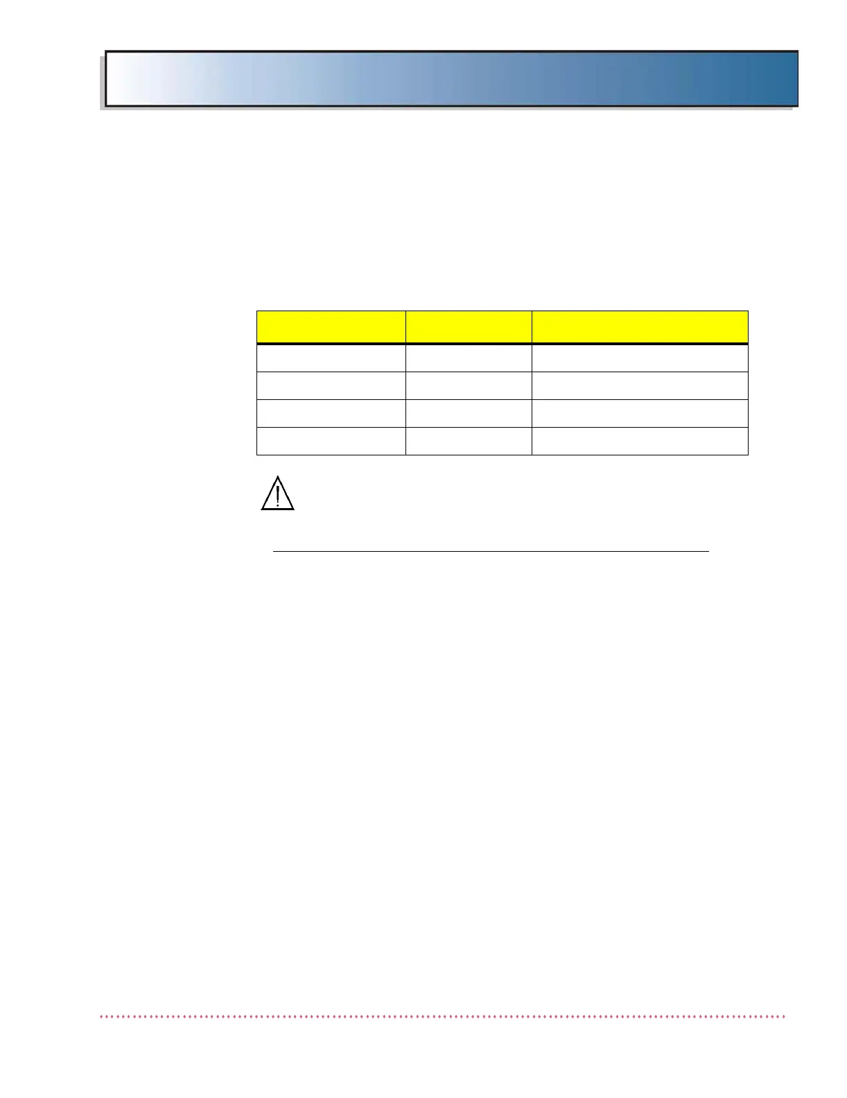
Typically, when the HF Series x-ray generator is shipped with an AID ICX ion
chamber, the chamber jumpers are pre-set in the following configuration:
CAUTION! The ion chamber must be electrically
isolated from the bucky to ensure proper AEC sys-
tem performance.
For systems equipped with universal type AEC (AEC Board AY40-027S):
Up to four ion chambers can be used. Connect ion chambers as follows:
• Wall#1 ion chamber to A11J8
• Wall#2 ion chamber to A11J12
• Table ion chamber to A11J10
• Auxiliary ion chamber to A11J13
Note that to connect a Siemens ion chamber AEC cable to universal AEC
Board A11 requires an interface cable assembly AY51-061 for each chamber.
This cable assembly adapts the ion chamber connector to 9-pin D-Sub type
used on the AEC Board, and provides a separate 300 VDC wire for connection
to A11TB1.
Route the ion chamber cable(s) as necessary to exit through the access open-
ing in top rear side of generator chassis, and secure as required. DO NOT
route through an opening containing a High Voltage Cable (see Figure 2-13).
Interfacing to Canon Digital Radiographic Receptor (When
Applicable)
The digital radiographic receptor is interconnected to the HF Series x-ray gen-
erator via Interface Board A9, P/N AY40-034T terminal blocks A9TB7 (Wall
Stand) and A9TB3 (Table), respectively, using 4-conductor, 18AWG cable.
Refer to the digital receptor manufacturer’s installation manual for more
detailed wiring instructions.
Table 2-5: AID ICX-153 or ICX-1153 Ion Chamber Jumper Configuration
JUMPER POSITION FUNCTION
61135A W1 1-2 & 3-4 LOW ACTIVE RESET
61135A W2, W3, W4 1-2 & 3-4 LOW ACTIVE FIELD SELECT
61135A W5, W6 1-2 & 3-4 A-B-C = 2-1-3
61135A W7 2-3 POSITIVE OUTPUT SIGNAL
 Loading...