Chapter 2 Assembly & Installation
HF Series X-ray Generators - Service Manual Revision W
Quantum Medical Imaging 2-23
Collimator Connections
Terminal block TB1 (see Figures 2-15 or 2-16 for terminal block TB1 location)
provides 24 VAC (TB1-1 and TB1-2) and chassis ground (TB1-3) outputs for
connection to a collimator. On systems equipped with a manual collimator,
verify jumper A9JP1 is installed; remove A9JP1 if system is equipped with an
automatic collimator.
Also available on terminal block TB2 is the COL RDY terminal (at TB2-4) for
connection to automatic collimator with "exposure hold" interlock (use CHAS-
SIS GND terminal TB2-7 for return). Refer to collimator manual for specific
connection details.
Tube Stand/Peripheral Equipment Connections
Interface Board A9 Terminal block TB2 (see Figures 2-15 or 2-16 for terminal
board TB2 location) provides +28 VDC (TB2-1) and +28 VDC RTN (TB2-2)
terminals for connection of a tube stand power input cable, when applicable.
Maximum load current is 1.5A at these terminals.
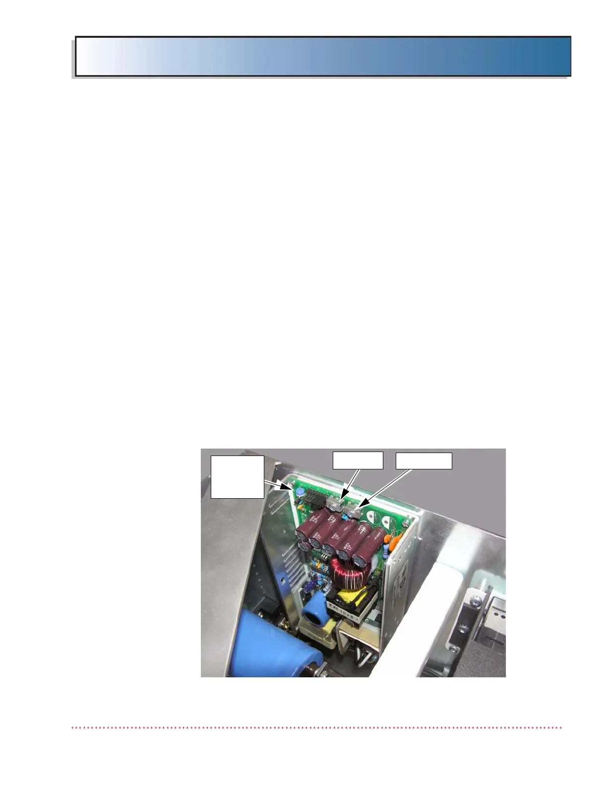
Internal +28 VDC Power Supply Option (QG-28VPS)
If generator is equipped with +28 VDC Internal Power Supply Option
(QG-28VPS), see Figure 2-16a and connect the tubestand/wallstand’s power
supply input leads as follows:
1. Positive lead to terminal P2-1 (+) on power supply
2. Negative lead to terminal P2-2 (-) on power supply
Figure 2-16a. Internal +28 VDC Power Supply Option (QG-28VPS) Location
P2-1 (+)
P2-2 (-)
OUTPUT
VOLTAGE
ADJ. POT.
 Loading...