Chapter 2 Assembly & Installation
HF Series X-ray Generators - Service Manual Revision W
Quantum Medical Imaging 2-25
RADIOGRAPHIC SYSTEM EQUIPMENT CONNECTIONS
The following paragraphs provide instructions for cable connections between the
HF Series x-ray generator and the x-ray tube, table, and wall bucky, as necessary.
Refer to Generator Interconnection Diagrams in Chapter 6, DIAGRAMS for addi-
tional guidance.
Ensure the generator is configured with the correct value rotor phase capacitor
C1 (on the Generator door) for tube installed in the system (refer to Table 2-2).
Tube Rotor Cable (Systems without High (Dual) Speed Starter
Option)
Route the X-ray Tube Rotor Cable AY51-014 through the middle cable access
opening located in the top rear wall of the generator chassis. Connect one
end of the cable to the appropriate terminals on Terminal Block TB1 on Rotor
Drive Board A10 (P/N AY40-013T) as shown in Figure 2-17. Connect the
opposite end to the X-ray tube’s terminal strip (refer to appropriate intercon-
nection diagram in Chapter 6, DIAGRAMS for tube connections).
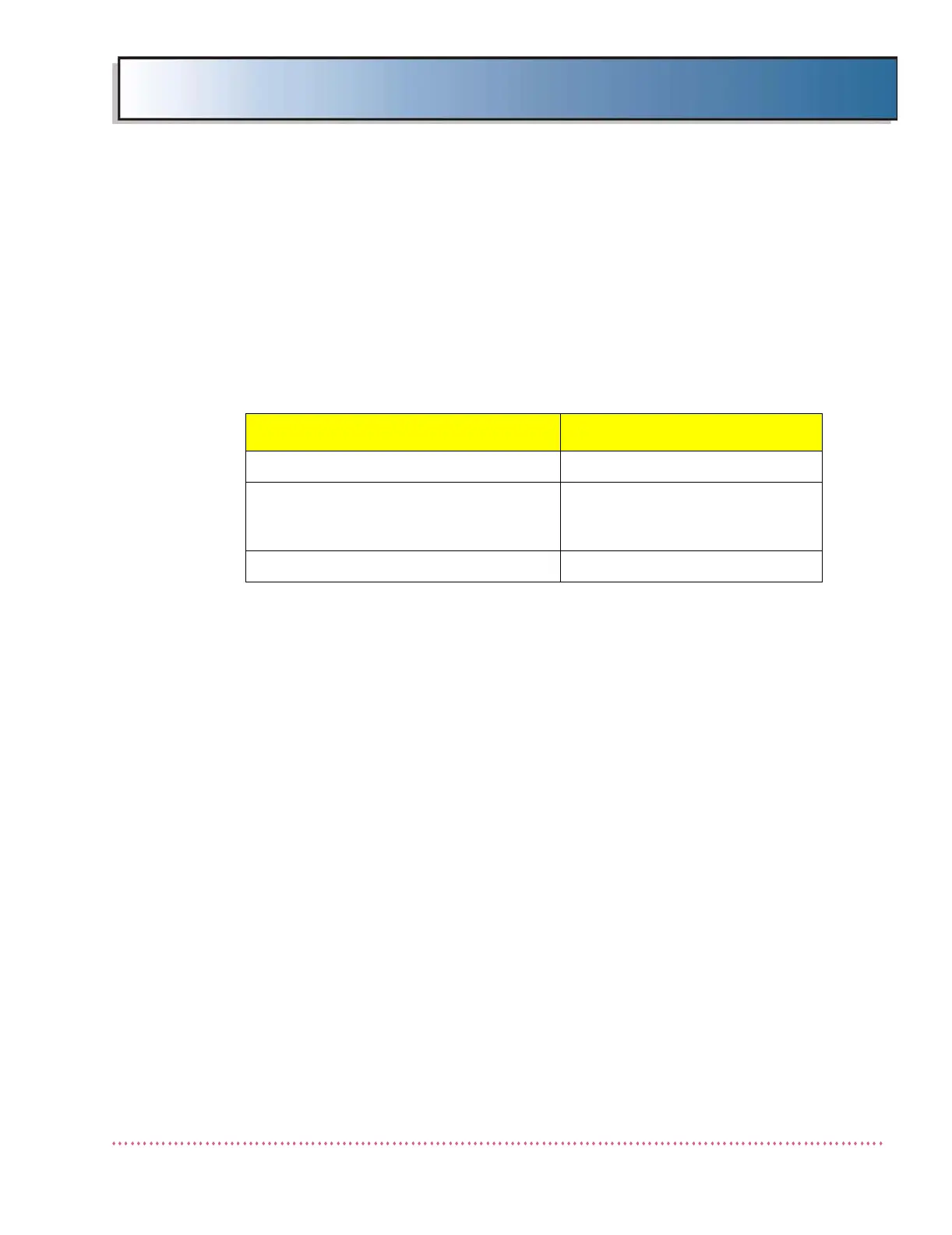
Table 2-2: Standard Single-Speed Rotor Phase Capacitor Configuration
Tube Type Rotor Phase Capacitors
E7239X, E7242X 25 uF
E7254X, E7255X, ALL VARIAN,
ALL DUNLEE (including MX100 Replace-
ment for GE Radiographic System)
30 uF
E7813X, E7252X 45 uF
 Loading...