Chapter 2 Assembly & Installation
Revision W HF Series X-ray Generators - Service Manual
2-10 Quantum Medical Imaging
Transformer Line Tap Adjustment (Single Phase SE Systems)
WARNING! Extreme care MUST be exercised to
ensure the safety of service or other personnel in
the area when working with live AC mains.
1. Using a calibrated DVM, measure the AC input (mains) voltage (i.e., line-
to-line or line-to-neutral, when applicable).
2. Verify that power to x-ray generator is disconnected.
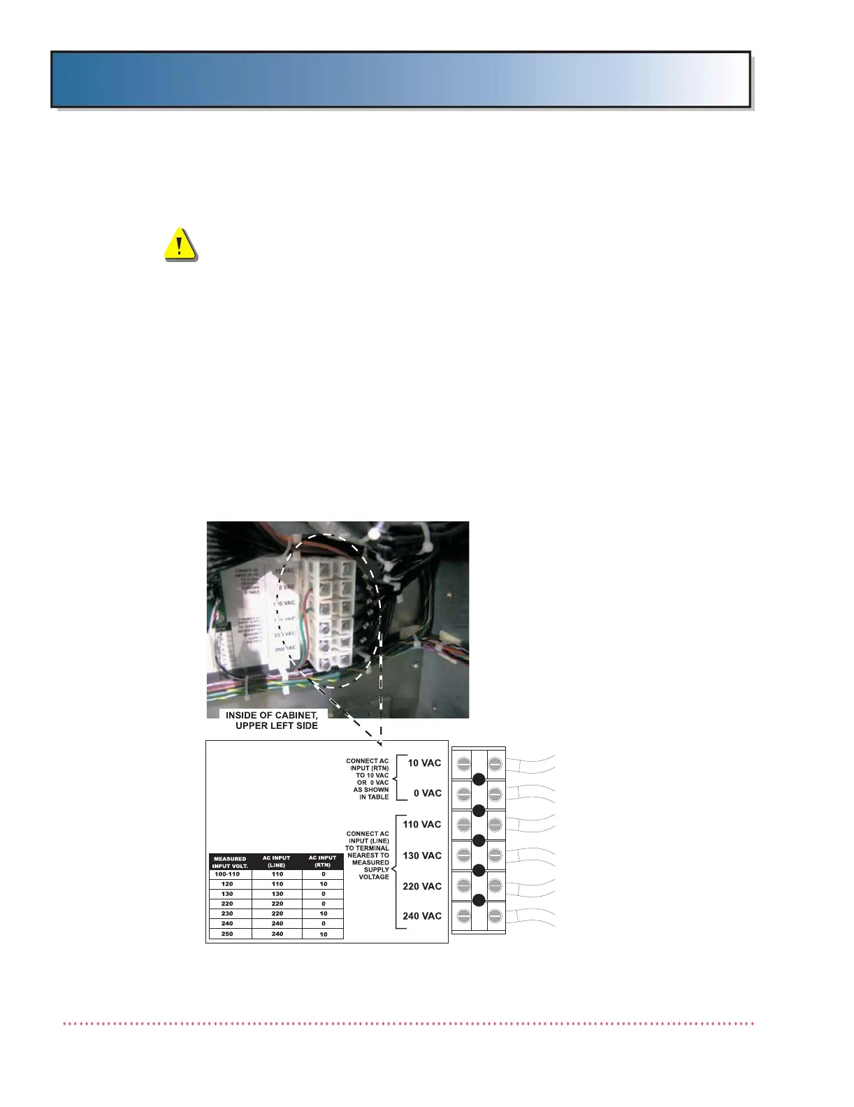
3. Adjust transformer taps by relocating the leads on the left side of trans-
former terminal block TB1 to match the input line voltage as closely as
possible. Refer to Figure 2-5 for STORED ENERGY (SE) input line tap
configurations.
6. Refer to Line Monitor/Battery Charger Board A8 (AY40-028T) Test Point/
Jumper Location Diagram in Chapter 6, DIAGRAMS and verify "line input"
jumpers are configured to match the line input supply voltage (115 or
230 VAC). Also, for 115 VAC line input configurations, fuses A8F5 and
A8F7 should be 2A; for 230 VAC line input configurations, these fuses
should be 1A.
Figure 2-5. STORED ENERGY Input AC Transformer Line Tap Connections
 Loading...