Chapter 2 Assembly & Installation
HF Series X-ray Generators - Service Manual Revision W
Quantum Medical Imaging 2-11
WARNING! Extreme care MUST be exercised to
ensure the safety of service or other personnel in
the area when working with live AC mains.
Proceed as follows:
1. Using a calibrated DVM, measure the AC input (mains) voltage (i.e., line-
to-line).
2. Verify that power to x-ray generator is disconnected.
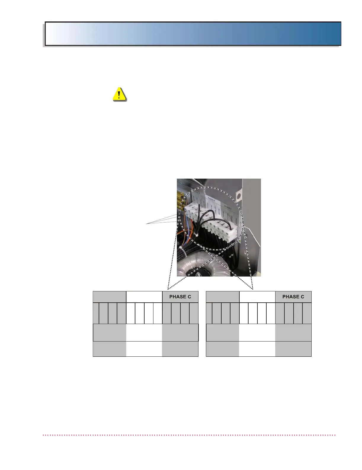
3. Adjust transformer taps by relocating the leads on the top side of trans-
former terminal block TB2 to match the input line voltage as closely as
possible. Refer to Figure 2-6 for input line tap configurations.
Figure 2-6. Three-Phase Input AC Transformer Line Tap Connections
4. For three-phase models, it is necessary to insure that the line resistance
meets maximum allowed as stated in Chapter 1, SPECIFICATIONS. If
line resistance exceeds the specification, the generator must be derated.
Refer to Chapter 3, CALIBRATION for derating instructions.
198 VAC
208 VAC
220 VAC
240 VAC
198 VAC
208 VAC
220 VAC
240 VAC
198 VAC
208 VAC
220 VAC
240 VAC
PHASE A PHASE B
LA40-056 REV. C
234523452345
380 VAC
415 VAC
440 VAC
480 VAC
380 VAC
415 VAC
440 VAC
480 VAC
380 VAC
415 VAC
440 VAC
480 VAC
380-480 VAC LINE INPUT CONFIGURATION
208-240 VAC LINE INPUT CONFIGURATION
TAP ADJUSTMENT
LEADS
 Loading...