Chapter 2 Assembly & Installation
Revision W HF Series X-ray Generators - Service Manual
2-12 Quantum Medical Imaging
5. On Line Monitor Board A8 (part number AY40-053S2 used on 380-480
VAC line input configuration, part number AY40-053S3 used on 208-240
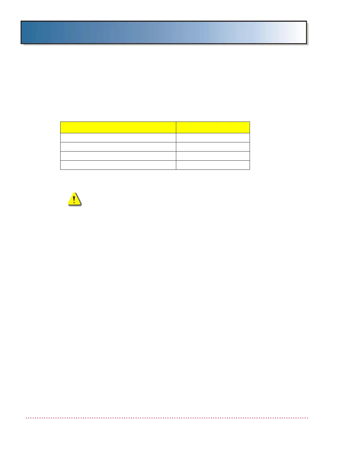
VAC line input configuration), verify 380/430/480 jumper is configured
correctly based on incoming line voltage measurement as follows (see
Line Monitor Board A8 Chapter 6, DIAGRAMS):
AC Input (Mains) Connection
WARNING! Verify incoming power supply (mains
disconnect) is turned OFF and all mains cables are
de-energized before connecting to the generator.
All electrical connections must be made in compliance with local and/or NEC
requirements. The generator is factory configured to accept line input speci-
fied when the order was placed. However, if it is necessary to change the
generator line input configuration, refer to the previous procedure entitled
"Transformer Line Tap Adjustment".
Non-STORED ENERGY (SE) version generators require a mains disconnect
box (with switch) before the x-ray generator (refer to your local code). This
switch should be within reach of the operator. A separate earth ground, #6
AWG insulated wire, must be installed. This wire must be the only wire con-
nected to the generator ground terminal.
AC INPUT VOLTAGE (MEASURED) JUMPER POSITION
342-403 VAC 380
404-459 VAC 430
460-528 VAC 480
198-252 VAC 240 (3 jumpers)
 Loading...