Chapter 2 Assembly & Installation
HF Series X-ray Generators - Service Manual Revision W
Quantum Medical Imaging 2-13
For non-SE generators, connect AC input cable as follows:
1. Mount cable clamp (included with system) to the hole on the lower right
or left side of generator cabinet chassis (see Figure 2-7).
Figure 2-7. Line Input Cable Clamp Installation
2. Route the AC input cable through cable clamp to Terminal Block TB1 and
tighten cable clamp.
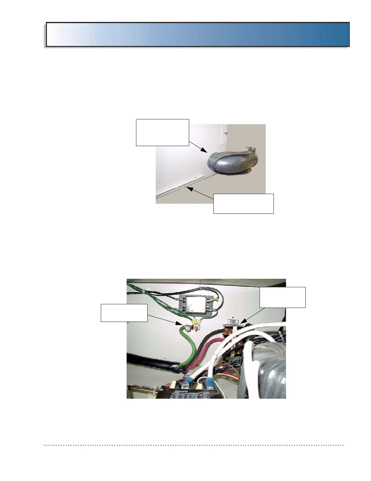
3. On single-phase systems:
a. Connect ground wire to ground lug mounted on rear wall of genera-
tor chassis, to the left of terminal block TB1 (see Figure 2-8).
Figure 2-8. Single-Phase Systems - Ground Lug and Terminal
Block TB1 Locations
GENERATOR
CHASSIS
LINE INPUT
CABLE CLAMP
(TYPICAL)
TERMINAL
BLOCK TB1
GROUND
LUG
 Loading...