Chapter 2 Assembly & Installation
HF Series X-ray Generators - Service Manual Revision W
Quantum Medical Imaging 2-21
INTERFACE BOARD SETTINGS & CONNECTIONS
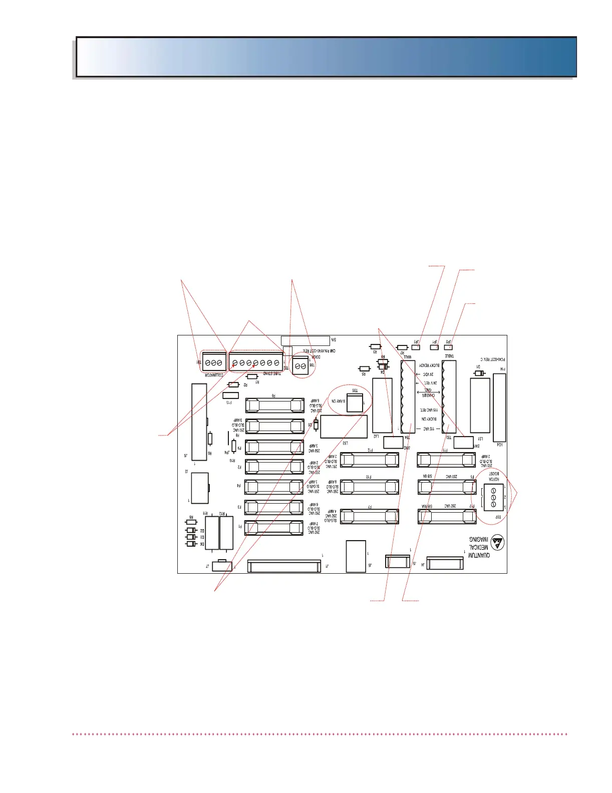
The generator’s Interface Board A9 provides the means for electrically connecting
external system components, such as collimators, tube stands, buckies, etc., and
verifying the correct Rotor Boost Voltage setting (non-high speed starter systems
only). Figure 2-15 shows connection locations on a typical non-digital (film-
based) system Interface Board; Figure 2-16 shows connection locations on a typ-
ical digital imaging system Interface Board.
Figure 2-15. Non-Digital System Interface Board A9 - Connection Locations
SLO-BLO
250 VAC
8 AMP
220VAC
110VAC
DOOR INTERLOCK
TERMINAL BLOCK TB6
TUBESTAND
TERMINAL
BLOCK TB2
COLLIMATOR
CONNECTIONS
TERMINAL BLOCK TB1
EXPOSURE
HOLD
CONNECTIONS
(AUTO COLL.)
X-RAY ON LIGHT
TERMINAL BLOCK TB5
JP1 INSTALLED
ON SYSTEMS WITH
MANUAL COLLIMATOR
JP2 INSTALLED
ON SYSTEMS WITH
NON-BUCKY TABLE
RECEPTOR
JP3 INSTALLED
ON SYSTEMS WITH
NON-BUCKY WALL
RECEPTOR
TABLE BUCKY POWER
WALL STAND BUCKY POWER
TERMINAL BLOCK TB4
MIDWEST BUCKY SWITCHES
(SEE TABLE/WALL BUCKY
CONNECTION INSTRUCTIONS)
TUBE ROTOR
BOOST VOLTAGE
JUMPER
(REV. R AND
HIGHER BOARDS
ONLY)
 Loading...