Chapter 2 Assembly & Installation
Revision W HF Series X-ray Generators - Service Manual
2-20 Quantum Medical Imaging
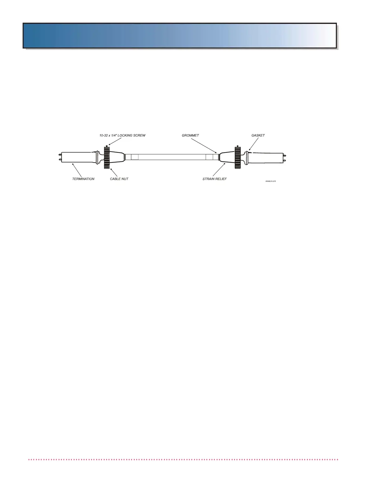
1. If not already done so, assemble onto the High Voltage Cable end a cable
retaining nut, grounding washer and strain relief (see Figure 2-14).
Ensure the 10-32 x 1/4" locking screw is turned out so as not to interfere
with engagement.
Figure 2-14. High Voltage Cable Assembly (Typical)
2. The High Voltage Cable terminals and tube housing and H.V. Tank recep-
tacles must be clean and dry. Be sure compression gaskets are in place
on the cable terminal.
3. To insure proper locking and grounding of the cable sheath, do not omit
the compression gasket on the cable terminal, as it is necessary for
proper contact between cable nut and flare.
4. Insert the cable terminal into the receptacle socket (watch the nipple on
the terminal to ensure correct positioning of the contact pins). Coat the
entire surface of the cable terminal insulator with insulating
compound (supplied with cables) using clean, dry plastic spoon
or wooden stick. Do not use fingers. Fully cover the entire surface
with a heavy coat (approximately 1/16" to 1/8"). Build a pyramid at the
tip of the terminal with the height of the compound even with the contact
ends.
5. With terminal key aligned with receptacle key way, insert the cable termi-
nal into receptacle until all excess compound has oozed out. Make sure
the contact pins are engaged in the holes in the socket insulator. Wipe
off any excess compound.
6. Tighten the cable nut while holding the cable firmly in place. Re-tighten
after calibration as some loosening may take place after the housing has
been heated and cooled. With cable nut properly tightened, secure with
10-32 x 1/4" locking screw.
 Loading...