Appendix B Calibration (DiRex System)
HF Series X-ray Generators - Service Manual Revision W
Quantum Medical Imaging, LLC B-27
A/D Calibration
The A/D (analog/digital converter) calibration utility is used to calibrate,
against a traceable calibrated voltage measurement instrument (such as a
DMM), various essential supply voltages utilized by the x-ray generator. After
A/D calibration has been performed, the A/D calibration utility may then be
used as a diagnostic tool allowing the technician to "read out" these voltage
measurements without having to remove the cover from the generator cabi-
net and without connecting a meter.
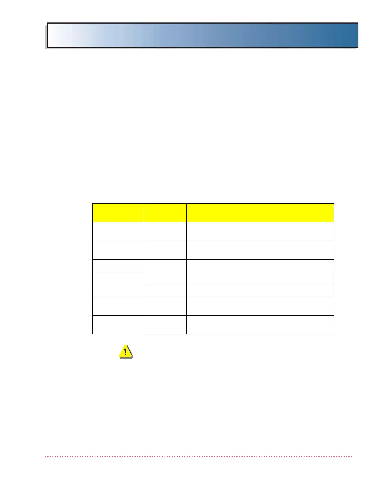
Table B-3 shows the various voltage levels (with tolerances) that can be cali-
brated using this utility, and it provides the location of the test point at which
a calibrated voltmeter must be connected for measuring the actual voltage
level:
WARNING! The following procedure requires that
power be applied to the generator. Extreme care
must be exercised to ensure the safety of service
or other personnel in the area.
The following procedure calibrates the generator to verify accurate system
measurement of the above operating voltages. The same procedure applies
to any of the voltage levels available for selection. Voltage measurement
accuracy is verified using your pre-calibrated voltmeter (traceable to NIST
standard) as the benchmark. Once calibrated, the generator’s CPU continu-
ously monitors these internal voltages and will terminate or not allow expo-
sure if specified tolerances are exceeded. Proceed as follows:
Table B-3. A/D Calibration Voltages
Voltage Level
Calibration
Accuracy
Test Point Measurement Location
Cathode ±8 VDC
+/- bus bars on Capacitor Bank next to Power Mod-
ule A19 (left side looking into generator cabinet)
Anode ±8 VDC
+/- bus bars on Capacitor Bank next to Power Mod-
ule A18 (right side looking into generator cabinet)
+5VDC ±0.1 VDC TP1 on Logic Board AY40-006S
+15VDC ±0.2 VDC TP3 on KVP Control Board AY40-003S
-15VDC ±0.2 VDC TP5 on KVP Control Board AY40-003S
Regulated +24 ±0.3 VDC
TP8 on Power Supply Board
AY40-005T
Unreg. +24V ±0.3 VDC
Terminal TB2-1 on Interface Board AY40-023T (or
AY40-034T)
 Loading...